In this section we will create two simple components, show various ways to bind connectors to geometry, and mate them with an Assembly Constraint. Then we will break a connector with a design change, and show how to repair it without breaking the contraint.
It is recommended, but not mandatory, that a component developer wraps components with an Assembly container and explicitly declares Constraint Connectors for use by component users.
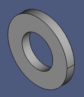
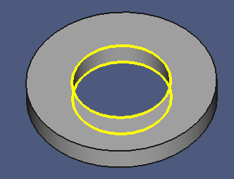
The Washer
A Washer
- Create a new project file, and save it under the name "asm.fcstd".
- Switch to the Part Design workbench.
- Select the asm project node in the model tree.
- Create a new Body.
- Create a new Sketch on the XZ plane.
- Create two circles with their center constrained to the sketch origin.
- Constrain their diameters to "8.3" and "16 mm".
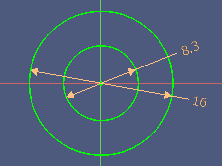
- Leave the sketch.
- Create a new Pad with a length of "2 mm".
Wrap the Body with an Assembly:
- Switch to the Assembly 3 workbench.
- Create a new Assembly.
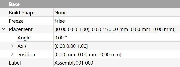
- Right-click on the Property Panel, then click Show all.
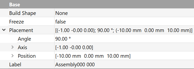
- Set the Label property to "Assembly000 000".
- Set the Label2 property to "Washer".
- Drag the Body node and drop it on the washer assembly.
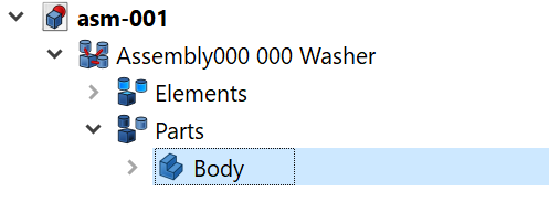
The Body appears under the Parts node of the washer assembly.
Now we will define the Constraint Connectors of the washer component.
- Select the Elements node.
- Set its Label2 property to "Constraint Connectors" to describe the purpose of this node.
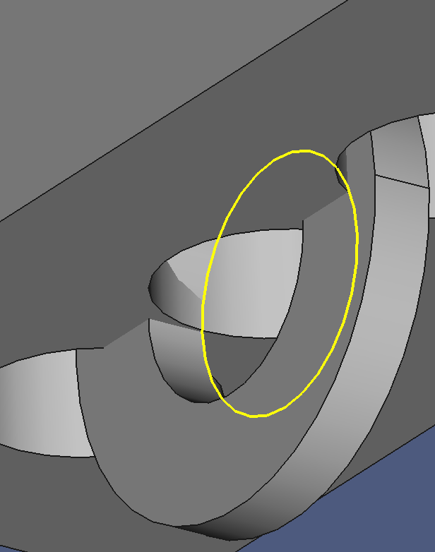
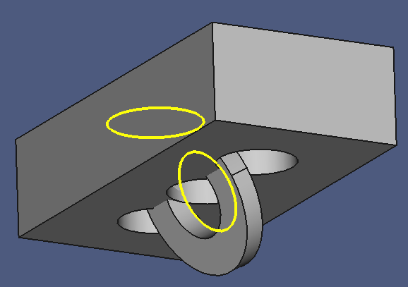
- Press "1" to select the front view, then tilt the view slightly back so that you have a clear view on both inner edges.
- Select the two inner edges if the washer body. These edges are owned by the Pad feature.
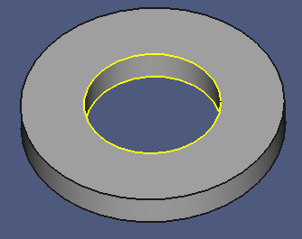
- Drag the Pad node on the Elements node.
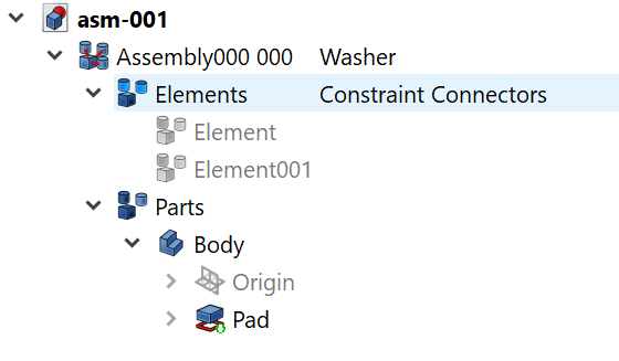
Two child nodes are created: Element and Element001. These are the Connectors that constraints can bind to. They are bound to the inner edges of the washer. If they are selected or if the mouse pointer hovers over them, they are highlighted in the 3D view.
Now we will provide a better identification for the connectors.
Depending on how you selected the edges in step 18, your connectors might have been assigned differently.
- Select the first Connectors child node, and verify the highlighted lower inner edge.
- Set the Label2 property to "Washer Lower Inner Edge".
- Select the second Connectors child node, and verify the highlighted upper inner edge.
- Set the Label2 property to "Washer Upper Inner Edge".
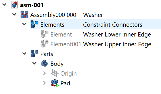
At this point, the washer component is finished. Some cleanup steps:
- Collapse all open nodes.
- Hide the washer assembly.
- Save a copy under the file name "asm-001.fcstd".
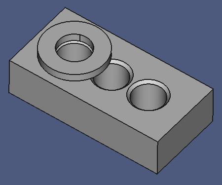
A Block Component
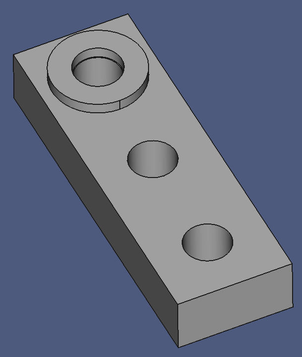
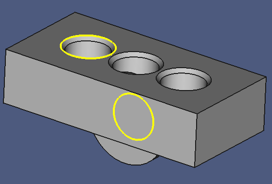
In this step we will define a simple block with a bunch of holes where we can attach the washers to.
To start here from scratch, …
- Open the file asm-001.fcstd
- Save as "asm.fcstd" to create the work file.
- Switch to the Part Design workbench.
- Select the asm project file node in the Model Tree.
- Create a new Body.
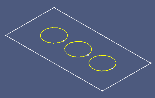
- Create a new Sketch on the XY plane.
- Create three circles with their center constrained to the X axis, and the middle one constrained to the sketch origin.
- Constrain their diameter to "8 mm".
- Constrain the center of the outer circles symmetrical to the Y axis.
- Draw a rectangle around them.
- Constrain the end points of a vertical edge symmetrical to the X axis.
- Constrain the end points of a horizontal edge symmetrical to the Y axis.
- Constrain the distance between the outer circles to "20 mm".
- Constrain the horizontal edge of the rectangle to "40 mm".
- Constrain the vertical edge of the rectangle to "20 mm".
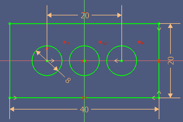
The sketch should be fully constrained now.
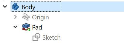
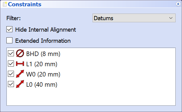
You can name the datum constraints according to this image:
- Leave the sketch.
- Create a new Pad, lenght = "10 mm".
- Press "0" on the keyboard to get a standard view on the component.
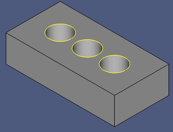
- Select the upper edges of the holes.
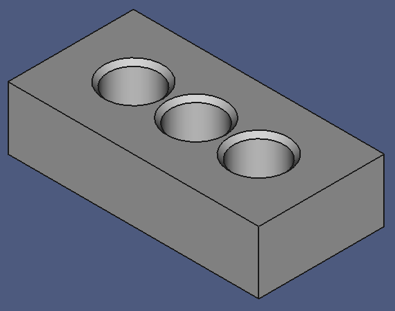
- Create a new Chamfer with a size of "0.7 mm".
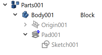
- Collapse Body001 and its child nodes.
We will now wrap the body with an Assembly container:
- Switch to the Assembly 3 workbench.
- Create a new Assembly.
- Right-click on the Property Panel, then click Show all.
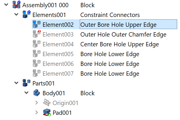
- Set the Label property to "Assembly001 000".
- Set the Label2 property to "Block".
- Drag Body001 on the block assembly.
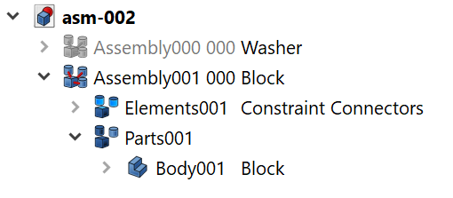
Now we will define the Constraint Connectors of the block component.
- Select the Elements001 node.
- Set its Label2 property to "Constraint Connectors" to describe the purpose of this node.
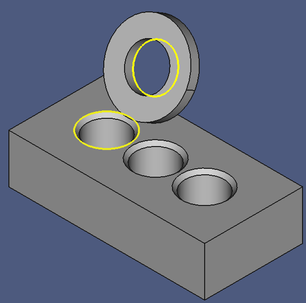
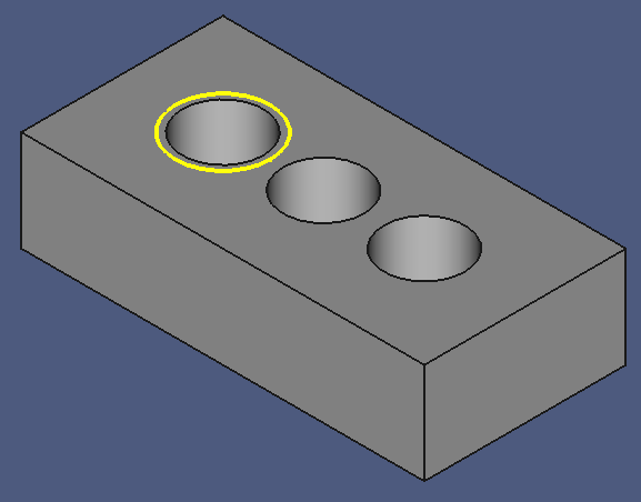
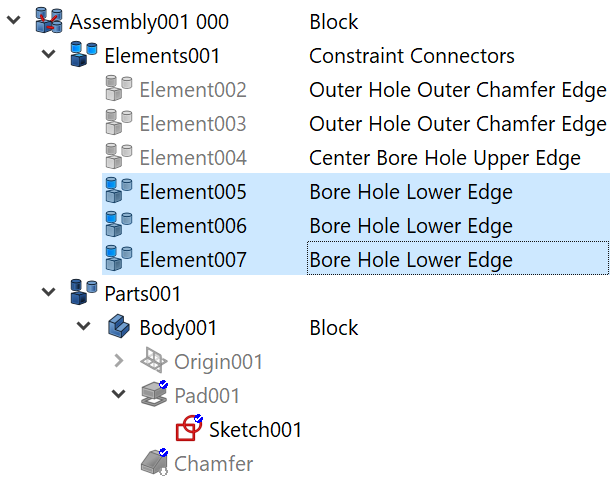
- Select the two outer chamfer edges of the outer bore holes. These edges are owned by the Chamfer feature.
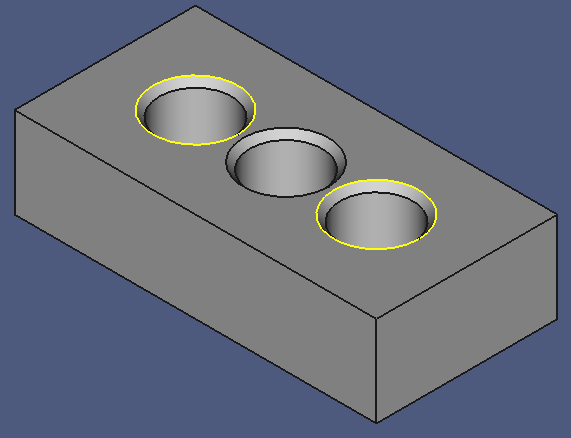
- Drag the Chamfer node on the constraint connectors node.
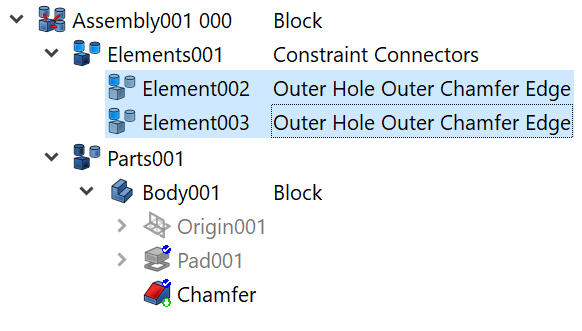
Two child nodes are created: Element002 and Element003. These are the Constraint Connectors that constraints can bind to.
- Select the two Connector nodes.
- Set the Label2 property to "Bore Hole Chamfer Outer Edge".
It is quite risky to bind a geometry element generated by a late feature such as this chamfer to a Constraint Connector. If an earlier Feature of the Body is modified, the edge names might disappear, or worse, might get a different meaning. We will investigate that and the implications later.
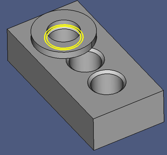
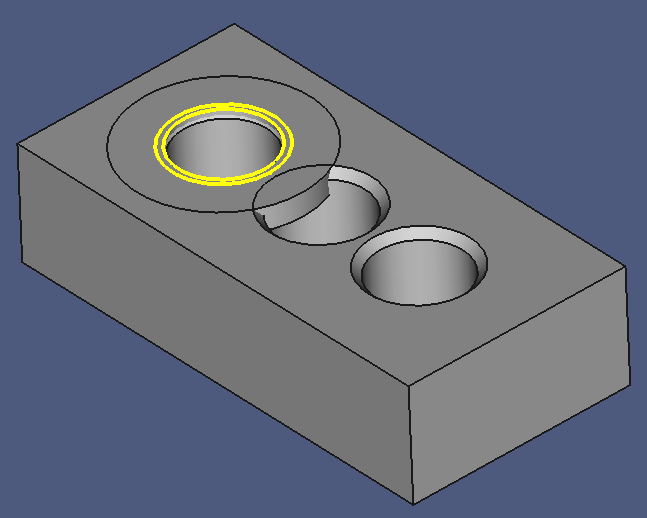
A better method is shown with the center hole:
- Select Pad001 and make it visible.
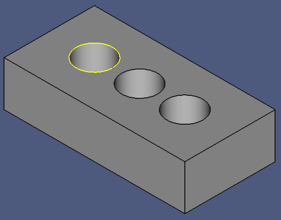
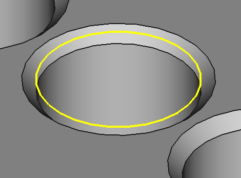
- Select the upper edge of the bore hole. It is owned by the Pad001.
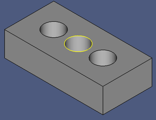
- Drag Pad001 on the constraint connectors node. This creates a new Constraint Connector in the Block component.
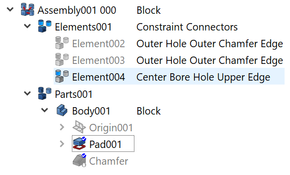
- Set its Label2 property to "Center Bore Hole Upper Edge".
- Select the Chamfer node and make it visible.
- Select Element004 and watch how it hovers in thin air above the chamfer.
Compared with the previous method, this Connector definition is more robust, because it was defined on an earlier Feature of the Body. However, there is still a better option:
- Hide the Chamfer node.
- Expand Pad001, and make Sketch001 visible. The circles lie on the XY base plane, on the same level with the underside of the block.
- Select the three circles in the 3D window. They are owned by Sketch001.
- Drag Sketch001 on the Constraint Connectors node.
- Set their Label2 property to "Bore Hole Underside Edge".
- Hide Sketch001 and show Chamfer.
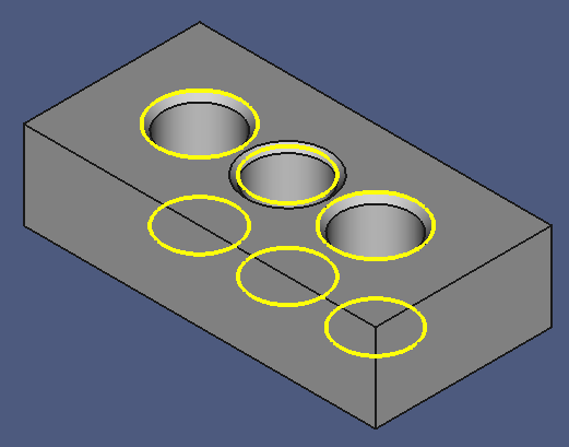
The block component is finished with six constraint connectors where things like washers can be mated with. We will try that in the next step. But before, some cleanup steps:
- Collapse the block and all of its child nodes.
- Make the washer assembly visible.
- Save a copy of the work file under the name "asm-002.fcstd".
Mating Washer and Block
Now is the time to get involved with Assembly Constraints.
It is necessary to have the model tree option Sync selection active to use this workflow. Click the menu View > Treeview actions, and make sure that the entry Sync selection is active.
To start here from scratch, …
- Open the file asm-002.fcstd
- Save as "asm.fcstd" to create the work file.
- Switch to the Assembly 3 workbench.
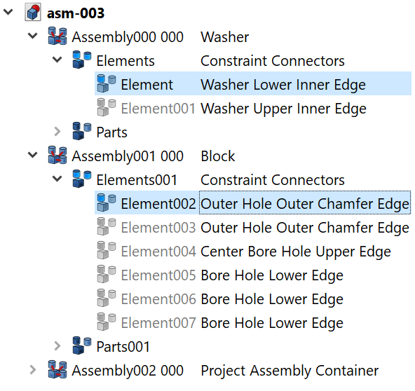
- Expand the washer's Constraint Connectors node.
- Select the Washer Lower Inner Edge connector.
- Expand the block's Constraint Connectors.
- Control-click to select the first Outer Hole Outer Chamfer Edge connector.
- With two Constraint Connectors selected, click the Plane Coincident constraint button on the Assembly 3 Constraints toolbar.
Oh. The toolbar is inactive. Let's activate it!
- Click the menu View > Toolbars > Assembly 3 Constraints.
Wait — the toolbar is already active! What's wrong here…?
The answer is simple if you know the answer: There is no Assembly container that can store the constraint. The container must contain the objects to be mated. So let's create one!
- Create a new Assembly.
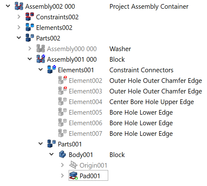
- Set the Label to "Assembly002 000".
- Set Label2 to "Project Assembly Container".
- Select the Elements002 node.
- Set its Label2 property to "Constraint Connectors".
- Save a copy of the work file under the name "asm-003".
Continue:
To start here from scratch, …
- Open the file asm-003.fcstd
- Save as "asm.fcstd" to create the work file.
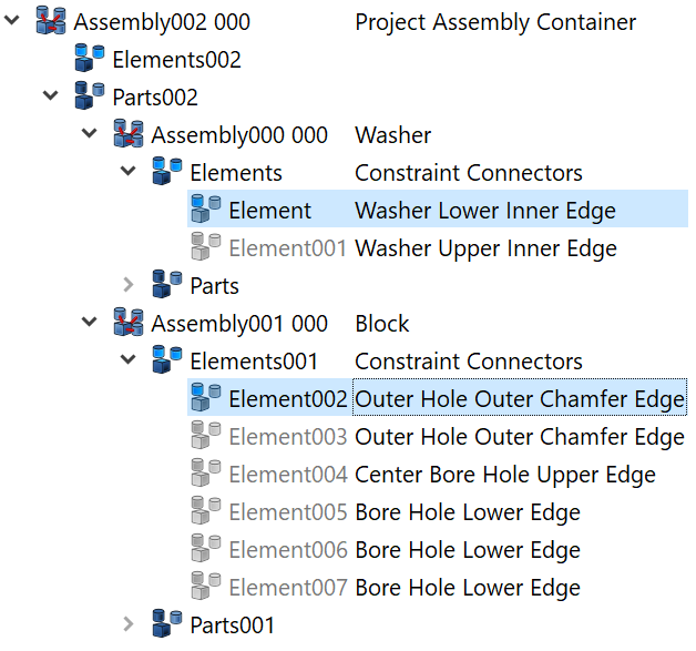
- Drag both block and washer assemblies on the project assembly container.
- Once again, expand the washer's Constraint Connectors node.
- Select the Washer Lower Inner Edge connector.
- Expand the block's Constraint Connectors.
- Control-click to select the first Outer Hole Outer Chamfer Edge connector.
- On the Assembly 3 Constraints toolbar, click the Plane Coincident constraint button.

The washer should have jumped to the bore hole. If not, …
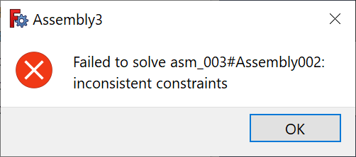
- Click the menu Assembly3 > Solve constraints.
Depending on the outside air temperature and the azimuth angle of the moon at a quarter to midnight, one of three things can happen:
- The washer jumped to its expected position, unfortunately in the wrong orientation.
- You get an error message:
- The washer jumped to its expected position and in the right orientation.
If option three happend, save all your files, shut down the computer, go out, have a beer or two and be happy.
To be honest: That never has happened to me…
Option 2 – Inconsistent Constraints
I'm not really sure what's the problem here, the error message does not really help out. I guess that the solver cannot decide in which direction to turn the washer so that the Connector planes become coplanar. So we will help a little bit and tilt the washer slightly:
- Undo the last command, assembly constraint creation.
- Right-click the washer, click Assembly > Axial move part. The well-known Translation Tool appears.
- Tilt the washer slightly, perhaps like so:
- Select the two connectors, as shown above.
- Click the Plane Coincident constraint toolbar button.
It happened that the toolbar remained inactive on the first try. Just deselect everything and try again. Et voil� — the washer jumped to the expected position. In the wrong orientation, of course.
Anyway, …
- Save a copy under the name "asm-004.fcstd" to have as state for retries.
Well, I'm not totally unhappy with the result, because now we can continue with…
Option 1 – Washer in Wrong Orientation
That's the situation:
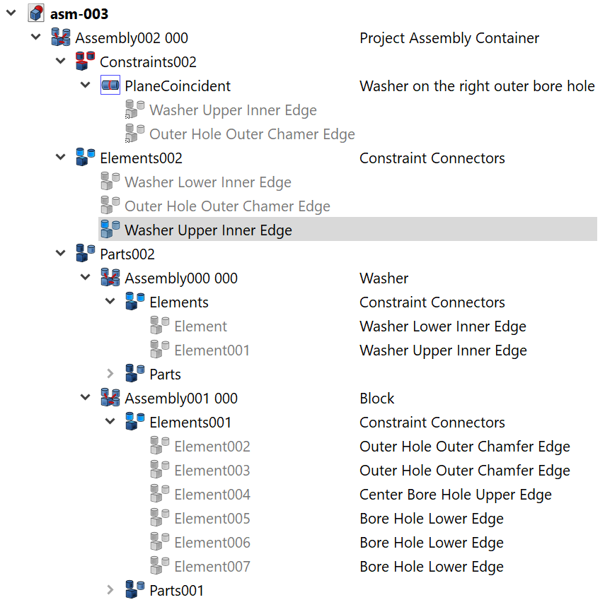
But let's see first what's happend in the Model Tree:
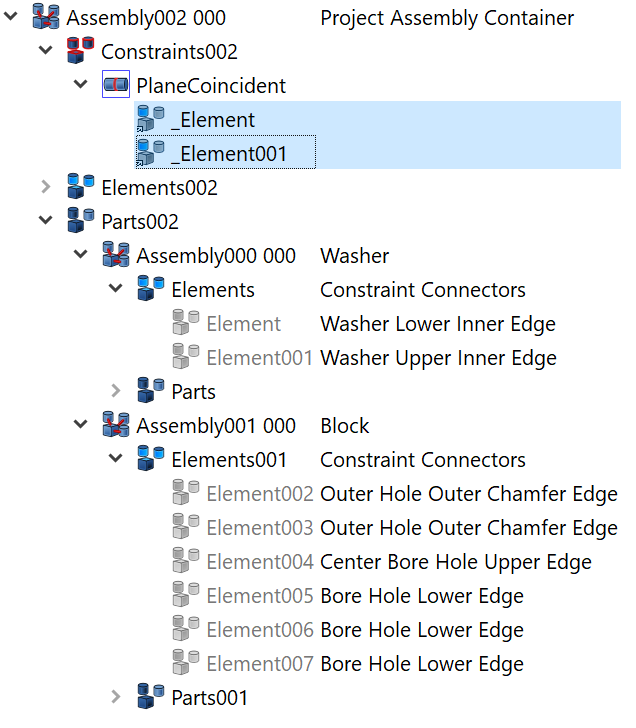
- The project assembly container has gotten a new child node, Constraints002. To be precise, the node was already there, but not visible.
- There is a new node named PlaneCoincident. This is our constraint that we just have created.
- The constraint node has two child elements, _Element and _Element001. These are Link objects that point to other nodes with the same name.
- Right-click the PlaneCoincident > _Element node, then click Select linked object.
This carries us to another node with the same name, but with a different parent, named Elements002, which holds the Constraint Connectors of the project assembly container. It appears that all connectors that were used in a constraint are automatically published in the Constraint Connectors collection of the container assembly.
- Set the description-Label2 of Elements002 to Constraint Connectors.
- Right-click the Elements002 > _Element node, then click Select linked object to follow the link chain to the next node.
And indeed, that takes us to the Connector described as Washer Lower Inner Edge.
Let's hold and think for a minute. On the previous page, we have defined that a project assembly container has no public constraint connectors, because a project is not intended to be mated with other assemblies. Clearly, the nodes in the Constraint Connectors child list are internal connectors. So if we find a way to designate them as "internal", we are back on track. A suggestion:
Elements with no Description in the Constraint Connectors collection are considered "internal". A "public" or "external" connector has a non-blank description string.
So if we leave everything as is, the world is all right.
Just to be curious:
- Select the node Elements002 > _Element.
- Set the Label to "Washer Lower Inner Edge".
- Select the node Elements002 > _Element001.
- Set the Label to "Outer Hole Outer Chamfer Edge".
Note that the Connectors under the Plane Coincident constraint also changed their names!
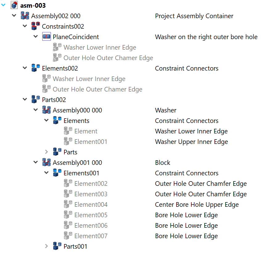
To complete the documentation work, …
- Select the Plane Coincident node.
- Set its Label2 to "Washer on the right outer bore hole", or something similar descriptive.
But now back to the problem: The washer is in the wrong orientation. We have three options to correct that:
- Use the washer's other connector.
- Bring the washer close to the desired position and orientation before creating the constraint.
- Dig through the properties of the constraint and see if we can find something useful.
Start with number three. Try the various angle properties. Nothing happens. Try the offset property. That works — but not an ideal solution.
Let's check number one.
- Expand Parts002 > Assembly000 000 > Elements.
- Select Elements001.
This is the washer upper inner edge. Inspect the edge in the 3D window. This could be the one.
- Drag Elements001 on Plane Coincident > Washer Lower Inner Edge.
This rebinds the constraint to a different connector. Note that the washer jumped into the desired position, finally. Also note that the label changed, it is now prefixed with an underline character. A look into the constraint connectors list shows a new entry, named "_Washer Lower Inner Edge". This is misleading, because it is the upper inner edge:
- Right-click _Washer Lower Inner Edge, click Select linked object. This selects the same named node in the Constraint Connectors collection.
- Set its Label property to "Washer Upper Inner Edge".
With this last action the tutorial is finished. Some final cleanup steps, as always:
- Collapse all open nodes.
- Save a copy under the name "asm-005.fcstd".
Conclusion
In this tutorial we have learned
- How to create an assembly component.
- Define its constraint connectors interface.
- Create a project assembly container to host the assembly components.
- Mate components by selecting constraint connectors and applying an assembly constraint.
- Pre-position components to help the solver deliver the expected result.
- Tweak constraint properties.
- Use Select linked object to find constraint connectors.
- Modify a constraint to use a different connector.
In the next tutorial, we will try the second option, prepositioning the components to be mated to help the solver deliver the expected results.