The Freecad User Book
The Architecture of Assembly Objects
Tags
Freecad, Assembly 3, Constraint, Connector, Architecture.
Freecad Version Info
OS: Windows 10 (10.0)
Word size of OS: 64-bit
Word size of FreeCAD: 64-bit
Version: 0.19.17089 +1543 (Git)
Build type: Release
Branch: LinkStage3
Hash: 950c082111ae5ebeefb4dddc90a80dc9b54b2408
Python version: 3.6.8
Qt version: 5.12.1
Coin version: 4.0.0a
OCC version: 7.3.0
Locale: English/United States (en_US)
The Nature of Constraints
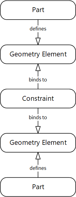
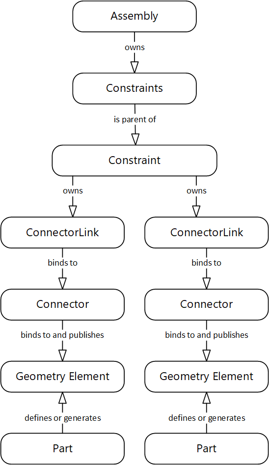
Figure 1 illustrates how an assembly constraint relates components to each other.
Figure 1
A part in this context is any Freecad object that defines geometry elements, such as vertices, edges or faces, to define its shape. An assembly constraint binds to these geometry elements, and thereby establishes a specific spatial relationship between the parts. To solve the relationship, the constraint modifies position and/or rotation of the related parts. Whenever the project model is recomputed, the constraints recompute position and orientation of the related parts in order to maintain their spatial relationship.
A constraint effectively reduces the degrees of freedom of movement of the objects against each other. In a three-dimensional space, we have a maximum of six degrees of freedom: Movement in the direction of the three coordinate system axes, and rotation around them. If the degree of freedom between components is zero, their position relative to each other is fixed. In other words, they are "glued" together, they are fully constrained.
Constraints in Assembly 3
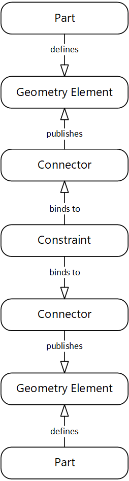
The Assembly 3 workbench adds an additional element, the Constraint Connector, or short Connector, to the scene:
Figure 2: Constraints Architecture in ASM3
A connector binds to a geometry element of a part in the assembly on one side, and offers an interface where constraints can bind to on the other side, thereby 'connecting' a constraint to a geometry element.
Please note that a connector in Assembly3 is called "Element", which gives some clue that there is a geometry element behind it, but does not suggest its purpose to the unknowing.
At first glance, the introduction of connectors seems to be pointless and add more work to the list, but there is a good reason behind: Connectors act as additional layer of indirection. This becomes evident when we examine how a model breaks when it is modified.
Breaking Models
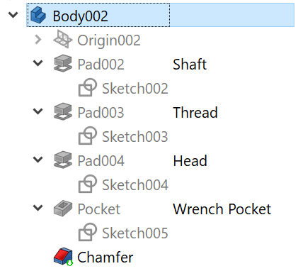
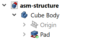
Let's assume a component created with the Part Design workbench, a Body. Such a Body consists of sequence of Features. Some of them depend on a Sketch.
Figure 3: Structure of a Part Design Body
When the project model is (re)computed, geometry elements are generated from these features, and they are named by some internal rules.
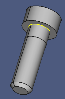
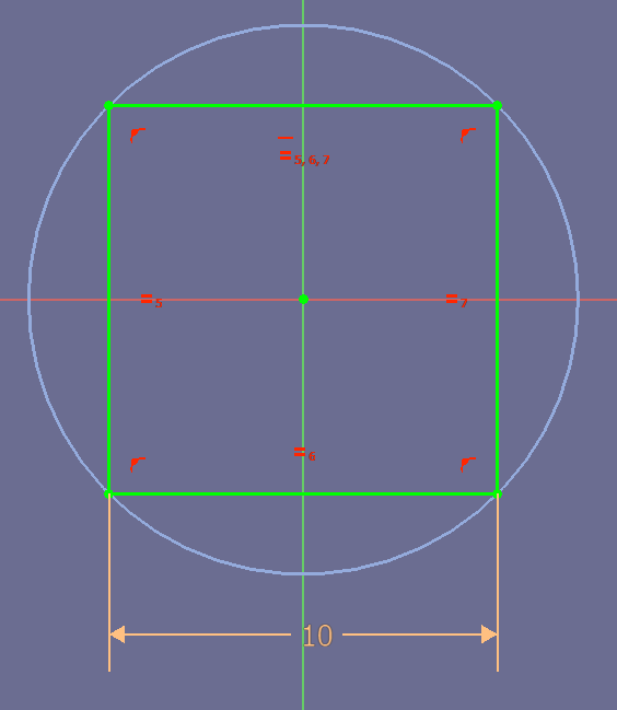
Take a look at the selected upper edge of the Shaft feature:
Figure 4: Selected Geometry Element in a Screw
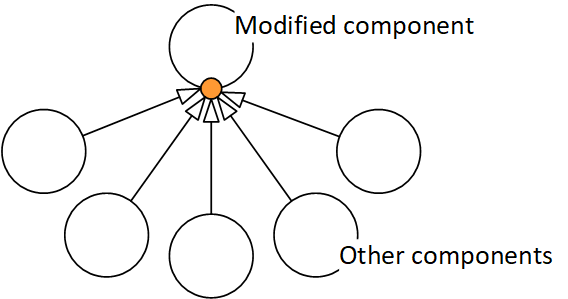
If the developer decides to remove the shaft feature, all constraints that use this edge will break. Figure 5 illustrates that in an abstract form. The orange dot represents the broken geometry element, the arrows represent constraints:
Figure 5: Broken Constraints
The problems arising from such design changes are known under the name "topo-naming problem". Search the Freecad Forum for the term. The discussions provide valuable background information.
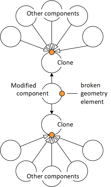
The problem can be solved, the developer simply binds the constraint to another suitable geometry element. But the problem is multiplied by the number of instances of the component in the project, the number of constraints binding to their breaking geometry, the number of documents, and the number of projects using this breaking component. Consider a standard component such as a bolt, which might be used in several hundreds of copies:
Figure 6: Broken Constraints Multiplied
The problem is multiplied, and so is the work for the developer.
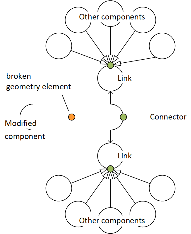
This is where the Assembly 3 Constraint Connector comes into play:
Figure 7: Model Integrity Maintained
Side note: The links are the Assembly 3 equivalent of the Clone.
A component developer is responsible to bind a Constraint Connector to an internal geometry element inside the component. When the component breaks, the developer rebinds the Connector to a different geometry element which serves the same purpose. The update appears in exactly one single place. The effect is that the Connector remains intact, and the model will not be broken by design changes.
Figure 7 illustrates another important architectural aspect: The entire component geometry is considered local or internal, the Connectors are considered their public interfaces. Their purpose is to publish an internal geometry element, and thereby isolate it from the outside world.
This is handled differently in the "traditional" model in figure 5, where the entire component geometry is considererd public.
The Structure of an Assembly
There are several node types that live in an Assembly node:
- Assembly
- A container object. Holds Parts, Elements and Constraints nodes.
- Elements
- Alias Connectors. A group node, holds a collection of Element (alias Connector) nodes.
- Element
- Alias Connector. Links to a geometry element of a Part in the Parts collection or to an Element (alias Connector) in a subassembly.
- Publishes that geometry element for connecting with a constraint.
- Constraints
- Group Node, holds a collection of Constraint nodes.
- Constraint
- Group node, holds a collection of ElementLink alias ConnectorLink nodes. Defines a geometrical relationship between parts by connecting to their elements (connectors).
- ElementLink
- Alias ConnectorLink. Child node of a Constraint node. Links (connects) to an Element (alias Connector).
- Parts
- Collection of Part or Assembly nodes.
- An Assembly in the Parts collection of a parent Assembly is called a subassembly.
- Part
- A Freecad object that generates a geometry (or geometry elements), or an Assembly object.
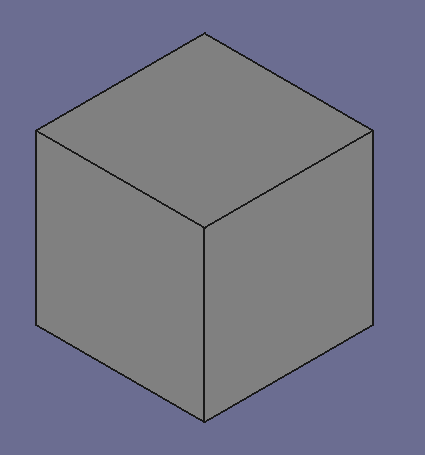
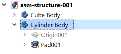
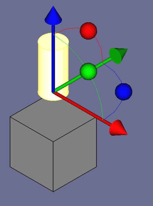
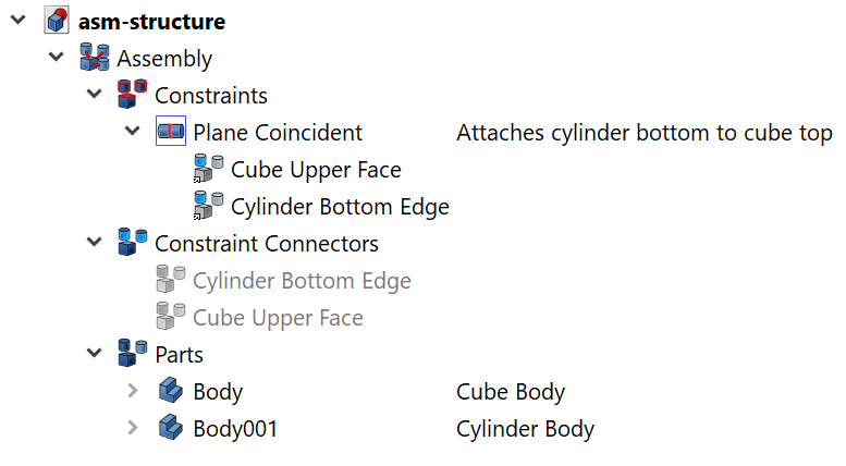
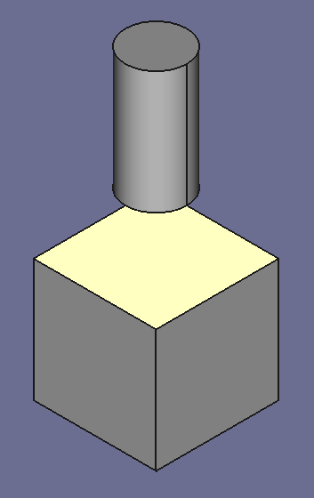
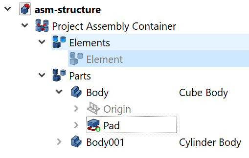
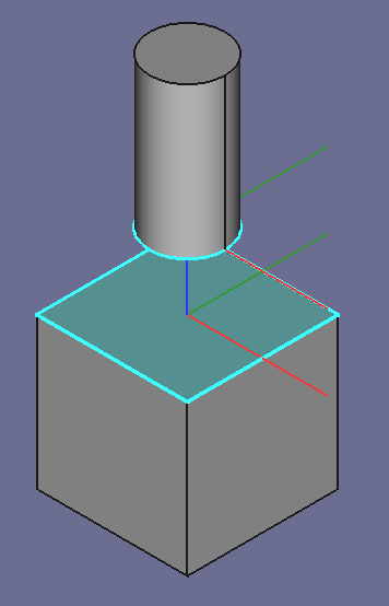
The following image shows an example of a simple Assembly:
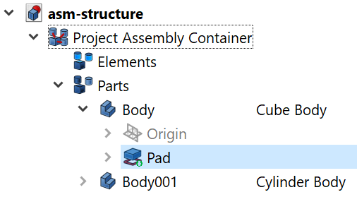
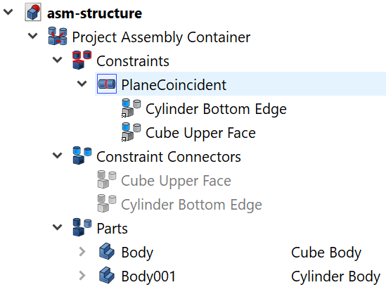
The cylinder bottom edge is constrained to the cube top face by a Plane Coincident Constraint. And here is the project file structure:
The Constraints, Elements and Parts group nodes are easy to find under the Assembly node.
Under the Parts node are two Part nodes (mind the distinct use of the plural s…). Both are Part Design Body elements, one defines the geometry of the cube, the other defines the cylinder.
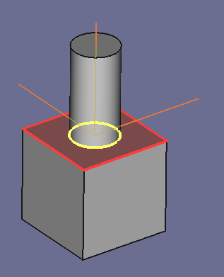
The Elements group node holds the Element nodes which define the connectors for assembly constraints. The first binds to the bottom edge of the cylinder, the other binds to the top face of the cube.
The Contraints group node holds a Plane CoincidentContraint node, which defines the geometrical relationship between cube and cylinder. Or, to be precise, between their constraint connectors. There are two ElementLink child nodes which link to these connectors.
With a little bit of imagination, you can recognize the structure of figure 2 in the assemly:
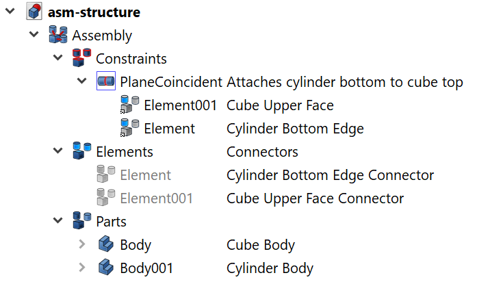
The following screenshot shows the same project file structure as above, but with renamed node labels. This should clarify the purpose of nodes:
Note the difference in the ElementLink and Element node icons:

The ElementLink has a link icon in the lower left corner, the Element icon has not — although both elements do link to another object:
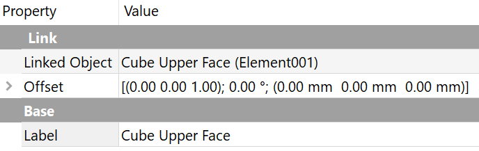
The ElementLink (alias ConnectorLink) links to the Element (alias Connector), and the Element (Connector) links to the geometry element Body.Pad.Face6:
In case of geometry modifications, you can easily point the Connector to a different geometry element, without breaking constraints.
Hands-On: Building the Assembly
Words can be confusing. And many words even more. So let's go for a test drive, and build the assembly that appeared in the screenshots of the previous section.
Files
Videos
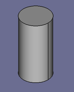
Cube and Cylinder Parts
The Assembly Container
Now we will create the project Assembly container. The first steps set up the configuration:
- Switch to the View > Workbench > Assembly 3 workbench.
- Make sure that the switch Assembly3 > Element style > Auto element visibility is "off".
This gives you manual control of the visibility of Connectors and ConnectorLinks in the 3D window.
- Make sure that the switch Assembly3 > Element style > Show element coordinate system is "on".
This gives you feedback about the orientation of a Connector in space (although not required for this tutorial).
- Make sure that the switch Assembly3 > Auto recompute is "off".
This allows you to manually solve constraints.

- Make sure that the switch View > Treeview actions > Sync selection is "on".
This makes sure that the associated feature node is selected in the Model Tree when you select a geometry element in the 3D window.
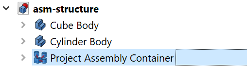
Now we can create the Assembly object:
- Click the menu Assembly3 > Create assembly.
- Rename the new assembly node to "Project Assembly Container".
A good point so save the status:
- Save a copy of the project file under the name "asm-structure-002.fcstd".
The next steps embed the two Body nodes in the Assembly container:
- Select both Body nodes
- Drag them on the Assembly node.
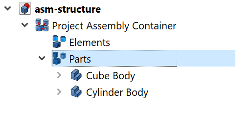
Notice that they appear now under the Parts group node.
Note that dragging parts on the Parts group node has the same effect as dragging them on the Assembly node.
- Save a copy of the file under the name "asm-structure-003.fcstd".
Creating Connectors
The next steps define the connectors which publish geometry elements to constraints.
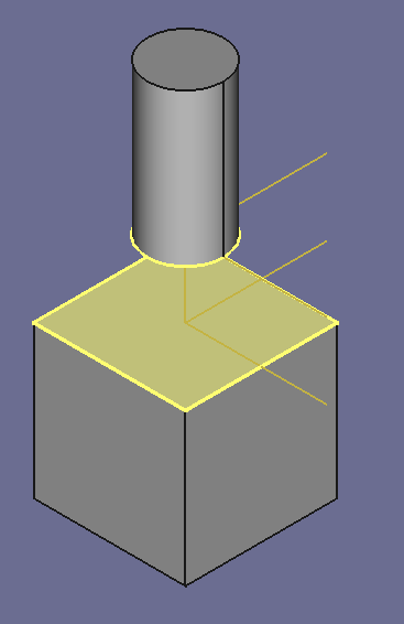
- In the 3D window, select the upper face of the cube.
This should select the Pad node in the Model Tree.
- Drag the Pad node on the Project Assembly Container > Elements group node.
This creates a new Element child node.
- Rename the Elements node to "Constraint Connectors".
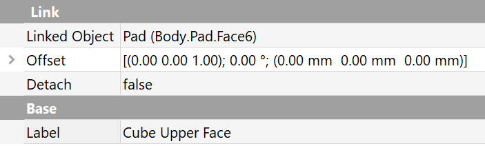
- Rename the Element (Connector) node to "Cube Upper Face".
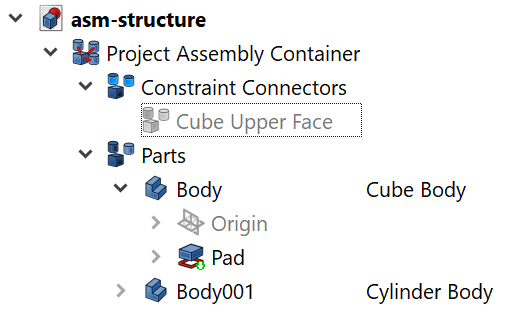
Now let's inspect the property panel of the connector. The Linked Object property value should be "Pad (Body.Pad.Face6)". This tells us that the Connector (Element) publishes Face6 of the cube.
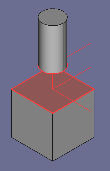
The next steps create a Connector that publishes the lower edge of the cylinder:
- In the 3D window, select the upper (!) edge of the cylinder.
That should select the Pad001 node in the Model Tree.
- Drag Pad001 on the Constraint Connectors node.
This creates a new child Element.
- Rename it to "Cylinder Bottom Edge".
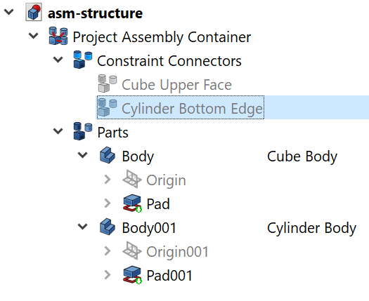
The Linked Object property should have the value "Pad001 (Body001.Pad001.Edge3)".
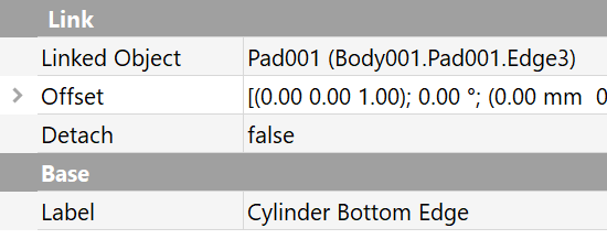
But wait! We wanted to publish the bottom edge, not the top edge!
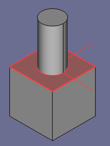
We could Undo the last Drop command and retry. But instead, the following steps show how to rebind the Connector to a different geometry object:
- Select the bottom edge of the cylinder in the 3D window.
That should select Pad001 in the Model Tree.
- Drag Pad001 on the Cylinder Bottom Edge connector.
- Inspect the Linked Object property.
It should now have the value "Pad001 (Body001.Pad001.Edge2)":
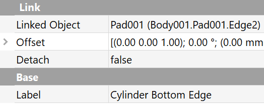
That's the right one.
This is the procedure to repair broken connectors when the component design was modified.
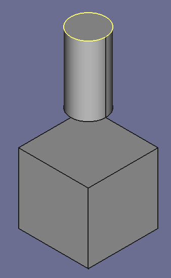
Constraint connectors are hidden by default.
- Make the constraint connectors in the Model Tree visible.
Making a Connector visible highlights the associated geometry element with the colors defined by the Constraint Connectors parent node:
Note that Connector and ConnectorLink themselves have no visual representation. Instead, the associated geometry element is highlighted or pronounced when required.
- Hide the connectors
- Save a copy of the file under the name "asm-structure-004.fcstd".
Creating the Constraint
Now we will define a constraint that binds to these constraint connectors:
- Select the connectors Cylinder Bottom Edge and Cube Upper Face.
- Click the Plane Coincident constraint button on the Assembly 3 Constraints toolbar.

There are changes in the Model Tree:
Creating the first constraint makes the previously hidden Constraints group node visible, and creates a Constraint child node, named after the type of constraint you selected. The Plane Coincident constraint has two ConnectorLink child nodes, Cylinder Bottom Edge and Cube Upper Face, both visible and selected by default:
If not selected, the geometry elements associated with the ConnectorLinks are highlighted in the color defined by one of their parent nodes, the Constraint Coincident, or the Constraints group node:
When hidden, the geometry elements are shown in their default colors.
ConnectorLink nodes link to Connector nodes with the same name:
- Right-click the Plane Coincident > Cube Upper Face ConnectorLink node, then click Select linked object.
The Constraint Connectors > Cube Upper Face node is now selected in the Model Tree.
- Right-click that node, and click Select linked object again.
That selects the Pad that generated the geometry element that is bound to the connector.
- Try the same with the Cube Upper Face ConnectorLink node.
A quick look on the scene in the 3D window reveals that the parts haven't moved yet, they are still in their initial position, although a constraint has been defined. The reason: Auto-recompute is "off". So we must do that manually:
- Click the menu Assmbly3 > Solve constraints.
Cube and cylinder should instantly snap together.
Final steps:
- Close all open nodes.
- Save a copy of the project file under the name "asm-structure-005.fcstd".
Checking the Constraints
- Right-click the cube Body node, then click Transform.
The Freecad Mover opens.
- Drag and/or rotate the cube, click OK to finish.
The cube moved, the cylinder stays in position.
- Click the menu Assembly3 > Solve constraints.
The cylinder jumps into the constrained position.
Note: Depending on your file, it is possible that the cube, the cylinder, or both objects change their position. To setup a part as fixed in the coordinate system of its Assembly container, you need to apply a Lock constraint on it. This will be shown later.
- Right-click the cylinder Body node, then click Transform.
- Move and/or rotate the cylinder.
- Click OK to finish.
The cube remains in position.
- Click the menu Assembly3 > Solve constraints.
The cylinder jumps back into its previous (contrained) position.
Now let's explore the effect of Auto-recompute:
- Set the switch in the menu Assembly3 > Auto-recompute.
- Right-click the cube Body node, then click Transform.
- Drag and/or rotate the cube
The cylinder jumps into the constrained position as soon as the mouse button is released.
- Click OK to finish.
- Right-click the cylinder Body node, then click Transform.
- Drag and/or rotate the cube
The cylinder jumps back into the constrained position as soon as the mouse button is released.
- Click OK to finish.
Now let's try an Assembly 3 Mover:
- Select the cube Body node in the Model Tree.
- Click the menu Assembly3 > Move part

- Drag an arrow-cross to move the cube straight.
- Drag a rim to rotate the cube across the rim axis.
- Drag a point inside the mover to rotate the cube axross multiple axes.
Observation: Cube and cylinder always stay togtether, the constraints are instantly resolved.
- Try the Axial Part Mover.

Same behavior as the Part Mover.
- Try the Quick Mover.

This one is different: The selected object can be moved freely, the other object(s) stay in place, until the mouse button is released. This is useful for large assemblies with many constraints, when the constrained objects are lagging behind the moved object.
Conclusion
Following the recommended safe workflow, you should have no problems to create an Assembly filled with a number of parts, publish their geometry elements as Connectors, and apply Constraints on a set of Connectors.
Summary