The Freecad User Book

Cube On Corner

Tags

Freecad, Exercise, Part Design, Sketcher, Cube, Corner, Rotation, Geometry Sketch.

Freecad Version Info

OS: Windows 10 (10.0) Word size of OS: 64-bit Word size of FreeCAD: 64-bit Version: 0.19.17089 +1543 (Git) Build type: Release Branch: LinkStage3 Hash: 950c082111ae5ebeefb4dddc90a80dc9b54b2408 Python version: 3.6.8 Qt version: 5.12.1 Coin version: 4.0.0a OCC version: 7.3.0 Locale: English/United States (en_US)

Files

cube-on-corner-001.fcstd
Finished project.

Instructions

Workfile Setup

  1. Create a new file.
  2. Save it under the name "cube-on-corner.fcstd".
  3. Create a new group node and name it "Repository".

Geometry and Helper Sketches

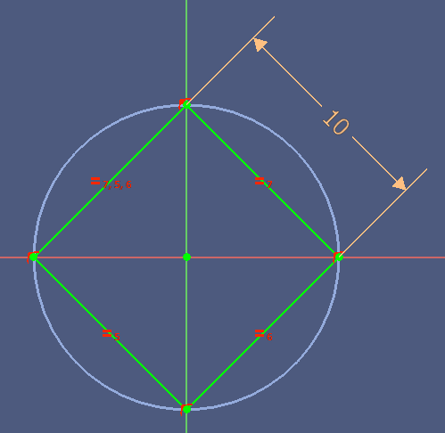
We begin with a Sketch that helps to calculate the rotation angle.

  1. Switch to the Sketcher workbench.
  2. Select the document node in the Model Tree.
  3. Create a new Sketch on the XZ Plane.
  4. Draw the following figure:

The lower edge points must be constrained to the x axis, and the edge must be vertical:

  1. Make sure you create (red) driving constraints. If not, click the menu Sketch > Constraints > Toggle reference/driving.
  2. Constrain the length of the vertical edge to "5 mm".
  3. Name the constraint "HSL".
  4. Constrain the length of the horizontal edge, and use the following formula:
    Constraints.HSL * sqrt(2)
  5. Name the constraint "HFDL".
    The sketch if fully constrained at this point.
  6. Click the menu Sketch > Constraints > Toggle reference/driving to create (blue) reference constraints.
  7. Click the menu Sketch > Constraints > Angle.
  8. Select the triangle's hypothenusis and the X axis to create an angular (reference) constraint.
  9. Name it "CDA".
  10. Select the triangle's hypothenusis and the Z axis to create an angular (reference) constraint.
  11. Name it "CCDA".
  12. Leave the Sketch.
  13. Rename it to "Sketch 000".
  14. Move the sketch node to the Repository folder.
  15. Hide the Sketch.

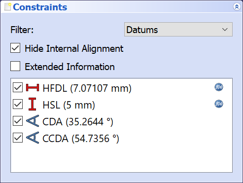
The constraint names have the following meaning:

HSL
Half of the Side Length
This value defines the cube side length, it will be twice this value.
HFDL
Half of the Face Diagonal Length
Half of the distance between opposite corners of a cube face.
The formula will be explained later we have created the cube.
CDA
Cube Diagonal Angle
The angle of the diagonal that lies on the XY plane.
CCDA
Complementary Cube Diagonal Angle
This is the angle we will have to rotate the cube to get it standing on the corner.

We continue with a helper sketch with a line on the z axis, which shall help to give a visual orientation.

  1. Select the document node in the Model Tree.
  2. Create a new Sketch on the XY plane.
  3. Draw a line, and constraint the end points to the Z axis.
  4. Constrain the end points symmetrical to the X axis.
  5. Constraint the length of the line and use the following formula:
    Sketch.Constraints.HFDL * 2 + 15 mm.
  6. Name the constraint "VLL" for "vertical line length".
  7. Leave the sketch.
  8. Rename it to "Sketch 001".
  9. Move the sketch to the Repository folder.
  10. Hide the sketch.

Creating the Cube

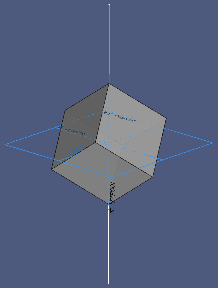
The next step creates the actual cube:

  1. Switch to the Part Design workbench.
  2. Select the document node in the Model Tree.
  3. Create a new Body.
  4. Create a new Sketch on the XY plane.
  5. Create a Square with the center constrained to the sketch origin, and one edge constrained to the X axis.
  6. Constrain the lenght of a side to the formula:
    2*Sketch.Constraints.HSL
    The result should be 10 mm.
  7. Name the length constraint to "SL" for "side length".
  8. Leave the sketch.

The sketch should look like the following image:

  1. Create a new Part Design > Pad with a length of "10 mm", symmetrical to the sketch plane.
  2. Set the length value to the expression "Sketch.Constraints.HSL*2".
  3. Check Symmetrical to sketch plane.
  4. Click OK to create the pad.
  5. Make the Body > Origin visible.
  6. Hide Origin > XZ Plane and Origin > YZ Plane.
  7. Press 0 on the keyboard to get into the standard isometric view.

Geometry Analysis

The top and bottom faces are parallel to the XY plane, and the vertical edges intersect with the X and Y axes:

  1. Hide Sketch 001.
  2. Show Sketch 000.
  3. Select the cube Body.
  4. Click the menu View > Appearance.
  5. Drag the Transparency slider to approximately 70%.

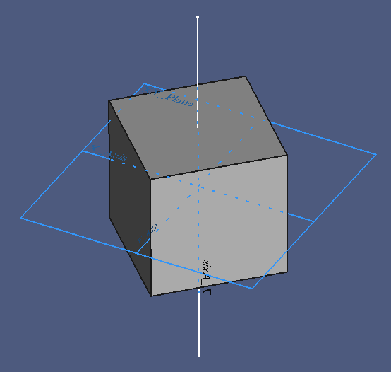
This makes our reference sketch inside the cube visible. A triangle leg rests on the XY plane, with the left end point on the origin of the body's coordinate system, which is also the center of the cube. The upper edge coincides with the upper right corner of the cube:

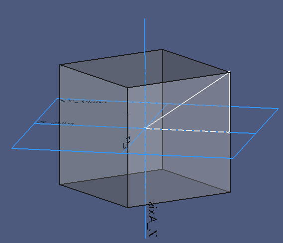
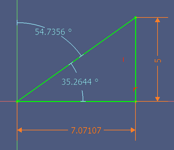
From this view we can easily derive the vertical leg of the triangle as half of the cube side length:

HSL = SL / 2

With a view from above, the length of the other leg is easy to find:

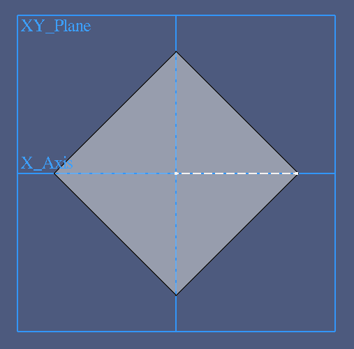
It is a cathetus of a symmetrical rectangular triangle between the origin and two corners of the cube. The hypothenusis is identical with the cube side length SL. Applying the Pythagorean theorem, we can find the length HFDL of a cathetus as

2 squ(HFDL) = squ(SL) squ(HFDL) = squ(SL)/2 HFDL = sqrt(squ(SL)/2) = sqrt(squ(SL))/sqrt(2) = SL/sqrt(2)

With SD=10 mm follows the half side diagonal length HFDL=7.071 mm

The angle near the sketch origin can be obtained with trigonometric functions:

CDA = atan(HSL/HFDL) = atan((SL/2)/(SL/sqrt(2))) = atan(SL/2/SL*sqrt(2)) = atan(sqrt(2)/2) = atan(sqrt(2)/sqrt(2)/sqrt(2)) = atan(1/sqrt(2)) = 36.26 deg

Note that the angle is independent from the size of the cube. The value is always 36.26 degree.

The complementary ange, CCDA, is the rotation angle we are looking for:

CCDA = 90 deg - CDA = 54.74 deg

These results confirm the values obtained from the graphical solution in Sketch 000.

Rotating The Cube Into Position

The next instructions rotate the cube about the Y axis:

  1. Select Body.
  2. Expand the Placement property.
  3. Expand the Placement > Axis property.
  4. Set Angle to the expression "90 deg - atan(sqrt(1/2))".
  5. Set Axis > y to 1.
  6. Set Axis > z to 0.

The local coordinate system of the body rotates with the body, so it is now more or less useless. Same with Sketch 000, but the helper sketch is helpful now. Hence the name…

  1. Hide Body > Origin.
  2. Hide Sketch 000.
  3. Show Sketch 001.
  4. Press 0 to get into the isometric standard view.

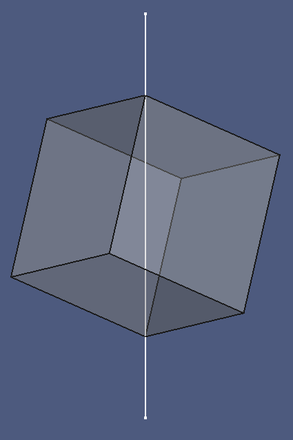
The cube stands on its tip. The helper line goes through the corners at the bottom and top.

A view from the top confirms the impression:
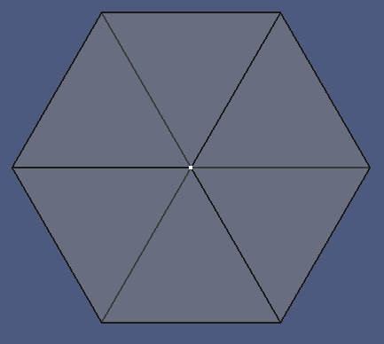
Q. e. d.

Cleanup Steps

  1. Close open nodes in the Model Tree.
  2. Save a copy under the name "cube-on-corner-001.fcstd".