The Freecad User Book
External Repositories
Tags
Freecad, Assembly 3, Link, External Link, Repository, External Repository, Replace With Link, Indirection, Link Layer.
Freecad Version Info
OS: Windows 10 (10.0)
Word size of OS: 64-bit
Word size of FreeCAD: 64-bit
Version: 0.19.17089 +1543 (Git)
Build type: Release
Branch: LinkStage3
Hash: 950c082111ae5ebeefb4dddc90a80dc9b54b2408
Python version: 3.6.8
Qt version: 5.12.1
Coin version: 4.0.0a
OCC version: 7.3.0
Locale: English/United States (en_US)
Files
Videos
In this section we will develop concepts to organize re-usable (standard) components in respositories. We already used a local repository inside the project file and links in the design to reference respository components. In these tutorials we will move standard components to an external repository. Such a respository can be shared among projects.
This tutorial borders, and how components can be organized in repositories.
We will demonstrate how Assembly 3 Links work across files, and how to repair broken links.
Moving Components to an External Repository
In this tutorial we will see how to move components from a project file repository in figure 25 to an external repository in figure 28.
Figure 27: Component in a local repository
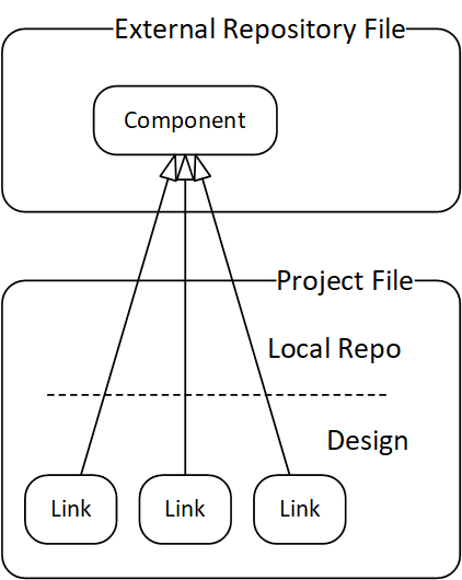
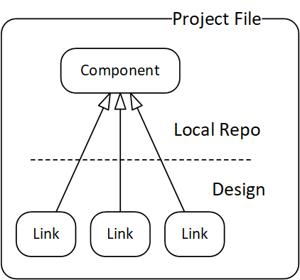 Figure 28: Component in an external repository
With drag & drop techniques, this should be a no-brainer. Unfortunately, the current version of Assembly 3 is not quite finished, and we will end up with broken links. This tutorial shows how to recover from such a situation.
Related Files
- Open the file link-011.fcstd.
- Save it under the work file name "xrepo.fcstd".
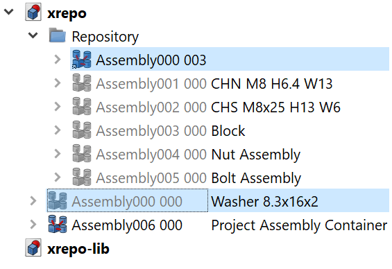
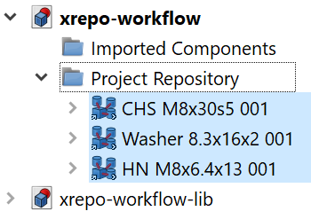
- Open the Repository node in the project file.
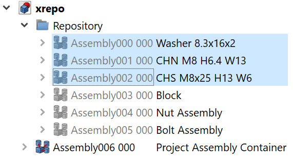
Here are the components used in the project. The first three are standard components, washer, nut and screw. These are likely to be re-used in other projects, so it might be a good idea to store them in a separate file.
- Click the menu File > New.
- Click the menu File > Save as... to save it under the library work file name "xrepo-lib.fcstd".
We will start with the washer component Assembly000 000, and move it to the new repository file.
- Save the project file xrepo. When asked to save the dependency files, click Yes.
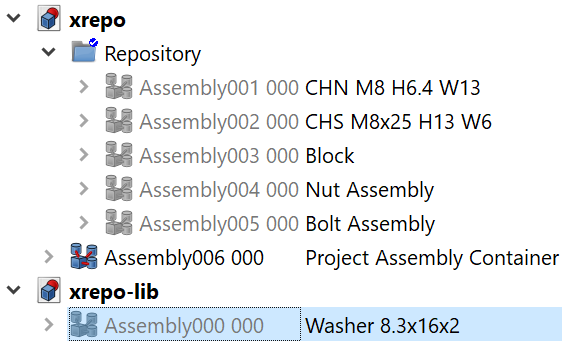
- In the Model Tree, drag the first (next) component Assembly000 000 from the local Repository folder and drop it on the external repository node xrepo-lib.
- Right-click the project file xrepo, click Mark to recompute.
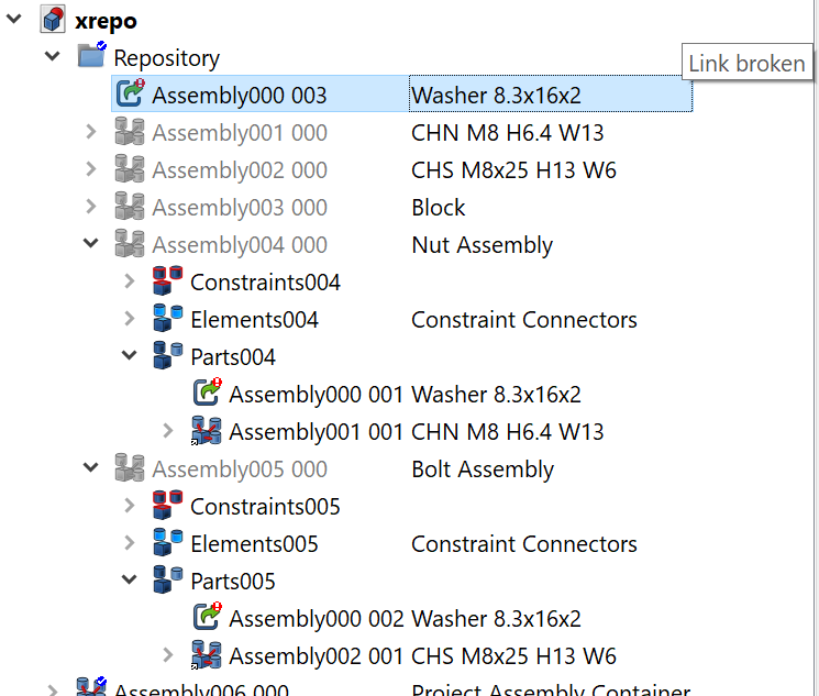
- Click the menu Edit > Refresh. Notice that the model tree unfolds to show two elements with an error icon.
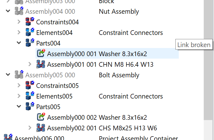
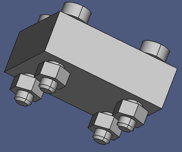
- Notice that the washers disappeared in the 3D window.
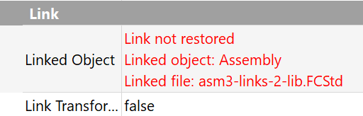
- Hover the mouse pointer over the broken tree nodes. An error text box appears and indicates "Link broken".
- Inspect the Linked Object properties of these elements: They are empty…
It appears that the current version of the Assembly 3 build is not yet quite finished in this area. So we will have to manually carry out the missing steps.
As mentioned above, the Linked Object property is empty. Fortunately, the Label value still gives a hint to what object we have to look for: Assembly000 000. This is a benefit of the strange naming convention I used for Links.
- Select the link node Assembly000 001.
- Click on the value field of its property Linked Object.
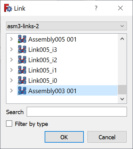
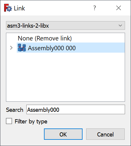
- Click on the button with the horizontal ellipsis that appears in the right corner. This opens the Link Dialog.
The link dialog window shows all model nodes of a file in a simple list.
- Select the entry xrepo-lib into the combo box.
- Enter "Ass" into the Search text box. This sets a filter for the listbox content, only assembly objects are listed now.
- Select the Assembly000 000 entry.
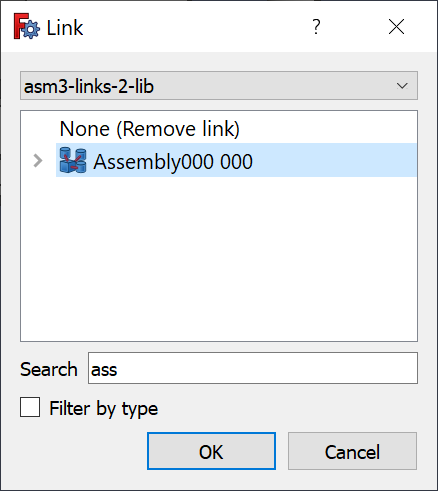
- Click OK.
The washers on the underside of the block re-appeared in the 3D window, but the node still has this error icon.
- Right-click the node, then click Recompute object.
The error icon disappeared, the node is OK now.
- Repeat from step 13 for the second broken model tree node.
The washers on the upperside should have reappeared.
To check whether there are still hidden errors in the project file you can…
- Collapse all nodes, right-click the project file node xrepo, and click Mark to recompute.
- Click the menu Edit > Refresh.
If nothing unfolds, the file is OK.
Now move the hex nut component:
- Repeat from step 6 with the Assembly001 000.
The hex nut component should be in the external repository now.
You can drag multiple nodes at once to the repository, but be careful not the screw up the link source fields with the wrong values.
The cylinder head screw will make problems. That is one of the reasons we saved the file before every transaction.
- Save project and repository files.
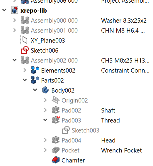
- Drag Assembly002 000 on xrepo-lib.
Note that not only the Assembly node was moved, but also some additional nodes: XY_Plane003 and Pad005, and Sketch006.
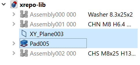
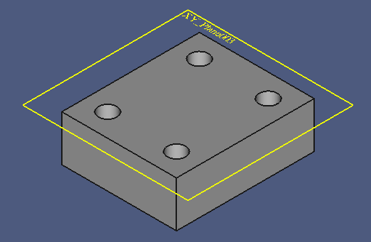
This indicates to an experienced user that Assembly002 000 has dependencies in the additional nodes. It is not quite easy to find them, but Pad005 in the 3D window looks like our Block component:
The following recipe shows a method to find the element(s) that causes problems:
- Delete Pad005 (and optionally Sketch006 and XY_Plane003) in the repository file.
- Ignore the warning and click Yes to continue.
The tree unfolds and exposes a node with an error icon, Pad003
- Select Pad003.
- Carefully browse through the properties.
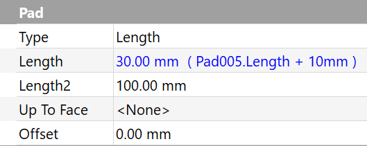
The Length property deserves your attention: The value is a formula, and the expression references Pad005.Length. This is the thickness of our Block component! The thickness determines the lenght of the thread.
It appears that the screw is not really a standard component…
We have now three choices:
- Revert the files, leave the screw in the local repository, and update the description.
- Undo the last two steps.
- Replace the formula in the thread lenght property with a constant value.
I have seen Undo to fail in this context, at least in the current version of Assembly 3, so reverting to the last stored file version seems to be the better option.
The third option will be chosen in the next tutorial, so we'll go for the second option, revert the files.
- Select the repository file.
- Click the menu File > Revert. Accept the warning.
- Select the project file.
- Click the menu File > Revert. Accept the warning.
- Change the screw description to "CHS M8 for Block Fasteners".
Cleanup:
- Collapse all nodes.
- Save the project file under the name "xrepo-001.fcstd".
- Save the repsitory file under the name "xrepo-lib-001.fcstd".
Conclusion
The steps to repair the broken links are relatively simple. The specific naming convention helps to identify the missing link source object.
Component Link Layer
An interesting concept to work with standard components is to use Links to a Link that links to a component:
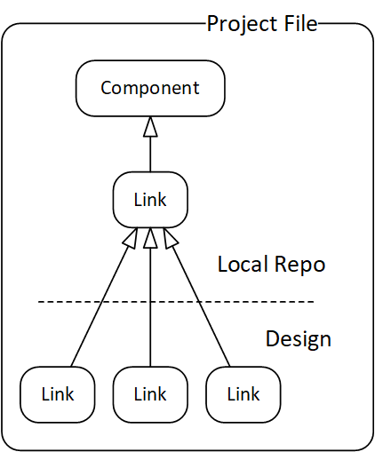
The component may be stored in the local repository in the project file initially. When matured, the component can be moved to an external repository:
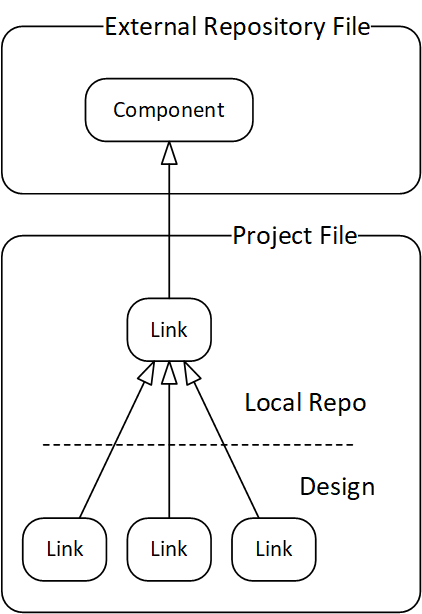
When used early in the project, this concept can save a lot of work. And as an added bonus, it is quite easy to work with variants:
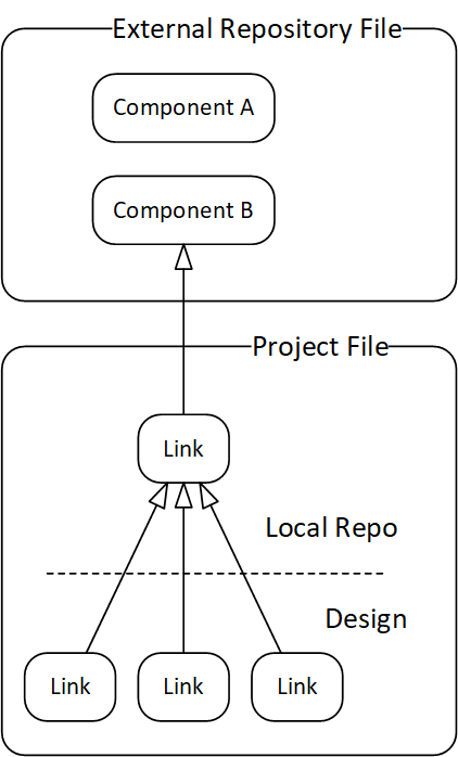
Only the local repository link has to be modified to point to the new component, all dependent links will inherit the change automatically.
This additional link layer can be created easily with the Assembly 3 Replace With Link function.
Related Files
- Open the file link-011.fcstd.
- Save it under the work file name "xrepo.fcstd".
- Open the Repository node in the project file. The first three nodes are the standard components that will be moved to an external repository.
- Click the menu File > New.
- Click the menu File > Save as….
- Save the new file under the work file name "xrepo-lib.fcstd".
Note that you must save an external repository file before a link into the file can be created, because the file name is part of the link information.
Now we will replace the first repository component with a Link:
- Right-click the washer node, click Link actions > Replace with link.
The component in the repository has been replaced by the link node Assembly000 003, and the component has moved down near the end of the model tree.
- Make sure to have hidden properties visible: Right-click on the Property Panel, click Select all.
- Copy the Label2 value from Assembly000 000 to Assembly000 003.
- Hide the link object Assembly000 003.
- Drag the component Assembly006 000 to the external repository node xrepo-lib.
Everything looks fine, but…
- Right-click the Repository node, click Recompute object.
The model tree unfolds and reveals three nodes with problems:
Fortunately, we already know how to deal with that:
- Select the first (next) problem node in the model tree.
- Click the Linked Object property value area.
- Click the button with the … at the right side to open the Link editor window.
- Select xrepo-lib into the combobox.
- Enter ass into the Search filter textbox.
- Select the Assmebly000 000 in the listbox.
- Click OK.
That repaired the link to the external component.
The remaining two problem nodes are treated similarly, except that their link source object Assembly000 003 is found in the local repository:
Note that new objects always seem to appear at the end of the list, so you don't always have to set a search filter.
To verify that there are no more problems with the file, …
- Collapse all expanded nodes.
- Right-click on the project file node, then click Mark for recompute.
- Click the menu Edit > Refresh.
If the project file is OK, no new problem nodes are unfolded.
- Click the menu File > Save to save the working copy of the project file.
- When asked to save the dependency files, click Yes.
- Repeat from step 7 with the second standard component, the hex nut Assembly001 000.
As we have learned from the previous exercise, the cylinder head screw Assembly002 000 causes problems because of a reference to Pad005.Length in the Pad003.Length value.
- Select the node Assembly002 000 > Parts002 > Body002 > Pad003.
- Discard the formula in the Length property, and set it to a fixed value of "35 mm".
- Collapse Assembly002 000.
Now the component is prepared to be moved to the external repository
- Repeat from step 7 for Assembly002 000.
Final cleanup:
- Collapse all nodes.
- Save a copy of the project file under the name "xrepo-002.fcstd".
- Save a copy of the repository file under the name "xrepo-lib-002.fcstd".
Conclusion
As we have seen in this example, the function Replace With Link creates an indirection layer for a component. Now the component can be moved, or even exchanged with a different component. This will be explored in the next example.
Replacing a Component
Assembly 3 Link objects make it easy to replace one component with another in the entire project, without breaking the project model. The only requirement is that both components, old and new, have the same public constraint connector names.
In this example, we will replace the cylinder head screw with a hexagon head screw.
We will create a new compontent in the external repository, and modify the link in the local repository to point to the new component.
Related Files
Step 1: Load the initial state files, and rename them to obtain the work files.
- Load the file xrepo-002.fcstd.
- Save the project file under the name "xrepo.fcsdt".
- Close the repository file xrepo-lib.
- Open the file xrepo-lib-002.fcstd.
- Save the repository file under the name "xrepo-lib.std"
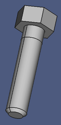
We will now create a second screw in the respository file.
- Switch to the Part Design workbench.
- Select the repository file node.
- Create a new Body.
- Create a new Sketch on the XY plane.
- Create a circle on the sketch origin.
- Constrain the diameter to "8 mm".
- Close the sketch.
- Create a new Pad with a length of 10 mm, reversed.
- Set Label2 to "Shaft".
- Select the underside of the Pad in the 3D window.
- Create a new Sketch.
- Click the menu Sketch > Geometries > External geometry > Defining
- Close the sketch.
- Create a new Pad with a length of 30 mm.
- Set Label2 to "Thread".
- Select to lower edge of the thread.
- Create a new Chamfer with a width of 1.2 mm.
- Create a new Sketch on the XY plane.
- Create a hexagon on the sketch origin.
- Set the distance between two parallel lines to 13 mm.
- Close the sketch.
- Create a new Pad, length 6.4 mm.
- Set Label2 of the pad to "Head".
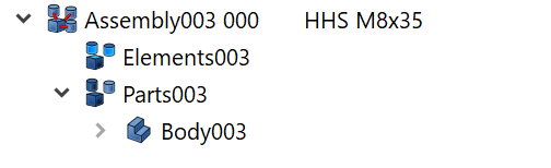
Wrap the new Body with an Assembly object:
- Select the repository file xrepo-lib.
- Switch to the Assembly3 workbench.
- Create a new Assembly element.
- Set Label to "Assembly003 000".
- Set Label2 to "HHN M8x35"
- Drag Body003 on Assembly003 000.
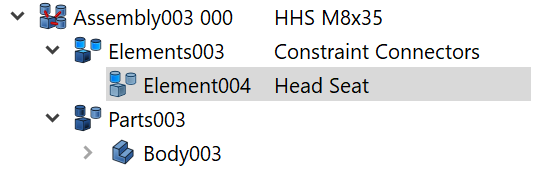
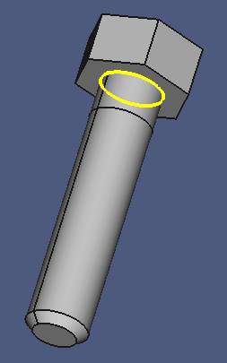
Create the constraint connector:
- Set Label2 of Elements003 to "Constraint Connectors".
- Select the edge between shaft and head in the 3D window.
- Drag the associated Pad007 on the Constraint Connectors node.
- Set Label2 of the new connector to "Head Seat".
To make the new screw compatible with the old one, the public constraint connectors must have the same label name:
- Select the Head Seat constraint connector of the cylinder head screw.
- Copy the Label property value.
- Select the Head Seat constraint connector of the hexagon head screw.
- Paste the Label property value.
The connector in the 3D window:
Obviously, it is possible to have duplicate Element label names!
NOTE that the internal name of the node ("Element005") now differs from the label value ("Element004"). Make sure that this is not a source of confusion!
Final cleanup steps:
- Collapse all open nodes.
- Hide Assembly003 000.
- Save a copy of the repository file under the name "asm2-link-2-lib-003.fcstd".
The repository is ready. Now we can exchange the screw in the project file.
Why not copy the cylinder head screw?
In the current preview version of Assembly 3, the copy function is not always reliable, and sometimes produces access violations, sometimes the copy dialog looks different. It is not clear whether the model structure is damaged, or not, so we will opt for the safe road.
- Open the Repository node in the project file.
- Select the screw component Assembly002 000.
- Click on the value field of the Linked Object property.
- Click the button with the horizontal ellipsis to open the Link editor dialog.
- Make sure the repository file is selected in the combobox.
- Set the Search filter to "***". (Censored)
- Select the Assembly003 000 entry.
- Click OK.
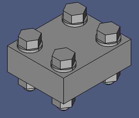
Et voil� — we have four new bolts in the project assembly!
- Copy the Label2 value from the repository component.
Now we will verify that the constraints in the project are still operational.
- Switch to the Assembly 3 workbench.
- Open the Block assembly node in the local Repository folder.
- Drill down to the Sketch006 node.
- Expand the Constraints property.
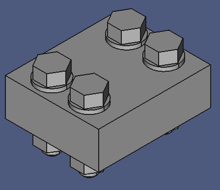
- Change the L2 value to "20 mm".
The fastener position should have changed.
- If not, execute the menu Assembly3 > Solve constraints.
Now the fasteners should have moved:
Conclusion
Instead of directly linking to repository components, an additional link layer in the local project repository opens an option to exchange components with other, compatible versions. To help migrating components, the Replace with link function was used. However, the the function is not yet perfect, some manual actions have to be carried out to fix broken links in the project.
Repository File Renamed or Moved
Repository files should never be renamed or moved. Such an operation breaks existing projects that depend on shared libraries. Unfortunately, reality is different. Servers go out of service, storage structures will be reorganized, project move to different computers.
The following tutorial deals with such a situation.
- Close all files in Freecad.
- Rename the respository "xrepo-lib.fcstd".
- Open the project file "xrepo.fcstd" in Freecad.
- Notice the broken links in the local Repository.

Fortunately, the Linked Object propety now carries a detailed error message:
So we can search for the repository file, and load it manually:
- Open the renamed resository file.
Now we can reassign the broken Linked Object fields. The error info specifies the name of the linked object, but this is the internal name, not the searchable Label value. Fortunately, our naming convention gives the hint to name to search for.
- Select the node Assembly000 003 in the project file.
- Click on the value field of the Linked Object property.
- Click on the horizontal ellipsis button to open the Link editor dialog.
- Select the repository file in the combobox.
- Enter the first part of the Label value (Assembly000) into the Search filter box.
- Select the matching entry in the listbox.
- Click OK.
The missing washer component re-appears in the 3D window.
- Repeat from step 6 for the other broken links.
- When done, right-click the project file node, then click Mark for recompute.
- Click the menu Edit > Refresh.
All broken links should have been repaired now.
Conclusion
Situations like these are another strong argument for an external components link layer in the local repository of a project file. This limits the number of broken links to the number of different components used from the repository.
If you linked directly to external components throughout the entire project file (the "quick & dirty" method...), the number of broken links would equal the total number of links to external components (in that repository).
Partial Loading
If you open a project that contains links to an external repository, the repository is also opened, but only the linked parts are loaded into memory. This space-saver allows you to work with very large libraries with a lot of "unused" parts inside, without having to worry about memory constraints.
If you explicitly open the repository, the entire library is loaded into memory. This allows to add links to other parts in the repository to the project.
If you close a repository file, the linked parts disappear from the 3D view. If you re-open the repository, the parts reappear.
If you open a different repository with the same parts but different implementations, these alternative parts appear in the project. This allows you to swap one repository file for another with different part implementations. The only requirement is that the internal names and the Connector names of objects are the identical in both repositories.
External Repository Workflow
In this section we will explore the recommended workflow with external repositories, and the effect of the object naming convention.
Files
As always, we begin with setting up the work files.
- Create a new project file.
- Save it under the name "xrepo-workflow.fcstd".
- Create a new Group node and name it "Imported Components".
- Create a new Group node and name it "Project Repository".
- Save a copy of the workfile under the name "xrepo-workflow-001.fcstd".
- Open the file xrepo-workflow-lib-001.fcstd.
- Save it under the work file name "xrepo-workflow-lib.fcstd".
This is our component repository.
Have a look at the component names (the Label property) in the repository.
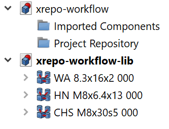
I used a key string that identifes the component and its main characteristics: A washer, a hex nut and a cylinder head screw. The composition of such a key string is usually company-specific, but there should be rules for naming standard components.
The other rule I recommend to follow here is the postfix " 000": This stands for the definition of a component.
The description string (in the Label2 property) was left empty, you can add additional information here that might be useful for selecting a component. Note that this information is not usually copied when a Link is created from a component definition.
In a project file, the Description should contain information about the purpose of a component in the design.
In the next step we will create links to some of the components and import them into the project:
- Select all three components in the xrepo-workflow-lib.
- Right-click on the selection, then click Link actions > Make link.
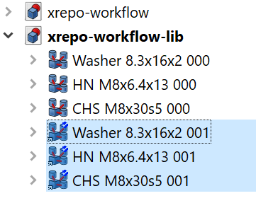
Three component Links are added to the repository file. Now we will move them to the local repository in the project file.
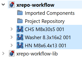
- Drag the selected Link objects in the repository on the project file node xrepo-workflow.
The Links moved to the bottom of the project file. They are still selected.
- Drag the selection on the Project Repository node.
- Drag the selection on the Project Repository node.
Currently it is not possible to drag the link objects from the repository and drop them directly on the group node.
Note the node names: The instance counter has been incremented to "001". In our naming convention this means that the node is a member of the indirection layer, and not to be used directly in the construction. The next steps demonstrate how to use them in the Project Assembly Container:
- Switch to the Assembly 3 workbench.
- Create a new Assembly.
- Rename it to "Project Assembly Container".
- Select the three components in the Project Repository.
- Right-click on the selection, then click Link actions > Make link.
- Drag the new links on the Project Assembly Container.
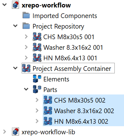
Note the instance numbers. A value greater than one indicates a component used in the construction. The workflow implements the scheme illustrated in figure 25:
The following table summarizes this relationship:
| Index |
Usage |
| 000 |
Component Definition |
| 001 |
Link layer in local repository |
| 002 |
Component links used in the project |
| … |
The naming scheme offers the following benefits:
- Components can be exchanged on the project level by changing the 001 link in the indirection layer.
- Broken links can be repaired by searching for the component with the same key string and the index 000.
- External repository components can easily be imported (into the dedicated folder) to create a self-contained project file.
Final project file cleanup:
- Collapse all nodes.
- Save a copy of the project file under the name "xrepo-workflow-002.fcstd".
The repository file was not changed, so we don't need to save it.
Import Links
There are situations where you want to move components from an external repository into the project file, for example to hand out the entire project so someone else in a single file.
This can be done with the Import Link command. The workflow is as follows:
- Open the file xrepo-003.fcstd.
- Save it under the work file name "import-link.fcstd".
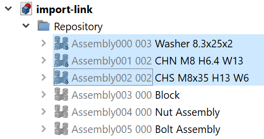
- Open the Repository folder.
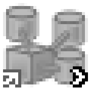
- Identify the external Link elements. They have a link icon in the lower left corner, and a chevron in the lower right corner.
You should be able to find three components:
- Select the identified components.
- Right-click on the selection, then click Import links.
Three new components were added to the project file.
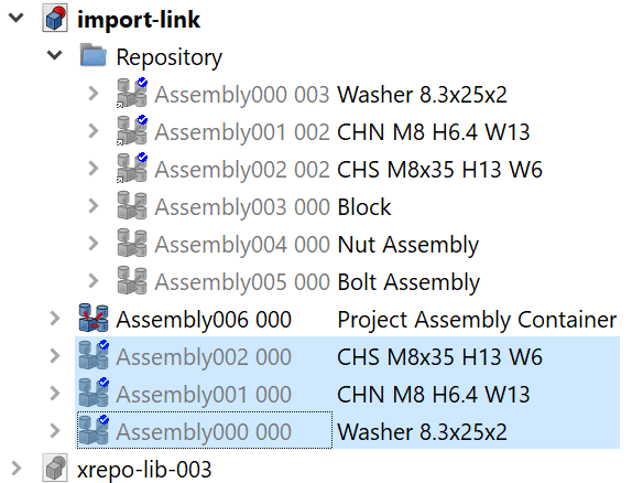
- Drag them to the Repository.
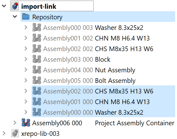
Note that their Label Names have not changed, and even the Description fields were copied from the external repository components.
Note that we now have the component definition (Assembly999 000) and the component indirection layer (Assembly999 009) in the repository. If we