The Freecad User Book
Visual Aids
Tags
Freecad, Assembly 3, Visual Aid, Constraint, Color, Highlight.
Freecad Version Info
OS: Windows 10 (10.0)
Word size of OS: 64-bit
Word size of FreeCAD: 64-bit
Version: 0.19.17089 +1543 (Git)
Build type: Release
Branch: LinkStage3
Hash: 950c082111ae5ebeefb4dddc90a80dc9b54b2408
Python version: 3.6.8
Qt version: 5.12.1
Coin version: 4.0.0a
OCC version: 7.3.0
Locale: English/United States (en_US)
Some visual aids can be used to help with constraints. On this page we will explore how they work, and how they can be engaged in a useful way.
Auto Element Visibility
The menu switch Assembly3 > Auto element visibility controls the visibility of Constraint Connectors, and how the are accented when the mouse hovers over its Model Tree element.
The switch has a system-wide scope.
Auto Element Visibility On
Constraint Connectors are highlighted in the preselection color when the mouse hovers over the Connector in the Model Tree. To be precise, not the Connector is highlighted, butj the geometry element that is bound to the Connector. The connector itself has no visible 3D element except its local coordinate system.
You cannot control the visibility of of a selected Connectors manually by pressing the space bar when this switch is on.
Auto Element Visibility Off
With Auto Element Visibility off, the visibility Connectors and the color of the associated geometry elements can be controlled manually.
Interestingly, a Connector has two Visibility flags on the property pages, one, on the View tab, and one on the Data tab. Both seem to have no effect, they appear to be read-only.
Override Material
If you set the Override Material property to true, the the element replaces the default color of child elements with the color set in the Connector Color property.
Connector Color
The color of the geometry element that is bound to a Connector is determined by three parent nodes:
- The actual Constraint parent node
- The Constraints grand parent node
- The Connectorsparent node.
The general rule is: A parent node overrides the colors defined by the child node.
The behavior can be customized with two properties on the View Tab of the Property Panel:
- Override Material (true or false)
- Shape Material (color)
If Override Material is true, the connector color is defined by the Shape Material color property. If Override Material is false, the connector color is shown in the color defined by the child node.
Connector Coordinate System
To examine the orientation of a Constraint Connector, a local coordinate system (LCS) can be shown on connectors. The LCS shows only positive axes, which makes it possible to recognize its orientation:
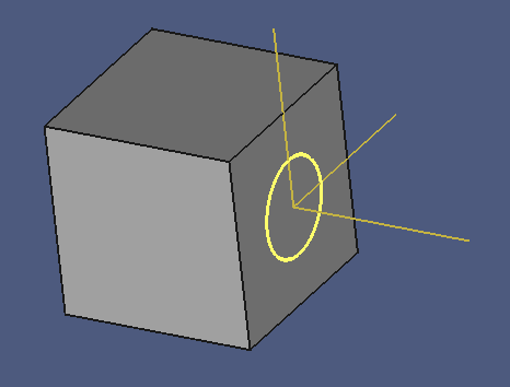
This is helpful when you orient components before applying an Assembly Constraint.
The switch can be found the menu Assembly3 > Element style > Show element coordinate system, and has a system-wide scope.
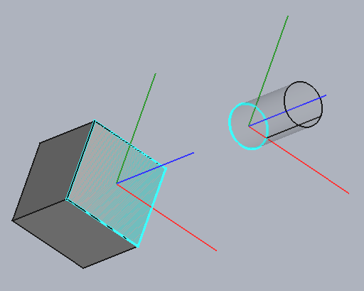
If the switch Auto element visibility is off and the connectors are made visible, the connector coordinate system are shown in colors:
Exercise
Words can be confusing, so here is a tutorial that walks you through the matter, step by step:
- Open the file constraint-colors-001.fcstd in Freecad.
- Save it under the workfile name "constraint-colors.fcstd".
- Switch to the Assembly 3 workbench.
- Open the menu Assembly3 > Element style > Auto element visibility, and turn it off. (The menu icon background should be grey.)
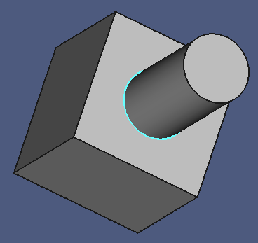
- In the Model Tree, select Assembly 002 > Constraints 002 > Plane Coincident 000 > Cylinder Bottom.
- Make it visible.
- Deselect Cylinder Bottom.
The lower edge of the cylinder, the that is bound to the connector, should light up in the default color.
- Select the Plane Coincident 000 node.
- Click the View Tab on the Property Panel.
- Set Override Material to true.
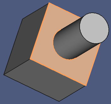
- Click the Shape Material value twice to open the Select Colors dialog.
- Choose a color of your choice, then click OK.
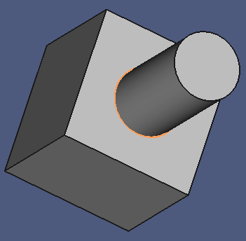
- Deselect Plane Coincident 000.
The cylinder edge should now show up in your selected color.
- Show Plane Coincident 000 > Cube Face.
- Deselect Plane Coincident 000 > Cube Face.
The constrained face of the cube should now have the selected color, too.
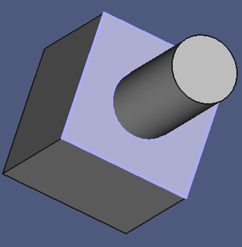
The parent node of Plane Coincident 000, Constraints 002, also has the ability to override colors:
- Select the Constraints 002 node.
- Click the View Tab on the Property Panel.
- Set Override Material to true.
- Choose a color of your choice, then click OK.
The geometry elements of the parts should now show your second color.
The Constraint Connectors of the two parts are also published under the Connectors 002 parent node, which has the same abilities:
- Hide Plane Coincident 002.
The connectors are no longer colored.
- Hover over the mouse pointer over the child nodes of Plane Coincident 002.
The connectors are not highlighted when the parent node is hidden.
- Select the child nodes of Plane Coincident 002.
The selection is not shown when the parent node is hidden.
- Make the child nodes of Plane Coincident 002 visible.
The connectors are still not shown in the 3D window.
- Hide the contraint connectors.
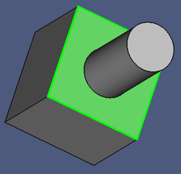
Now let's move to the Connectors 002 group and child nodes.
- Make Connectors 002 > Cube Face visible.
- Select Connectors 002.
- Click the View Tab on the Property Panel.
- Set Override Material to true.
- Choose a third color into the Shape Material property.
- Deselect Connectors 002.
The cube face should now show your third selected color.
Note that you cannot set the color of constraint connectors individually. The color set is always determined by their parent node. Hint: Constraint connectors have no Override Material property.
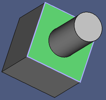
An interesting effect appears if two separate links to the same connector are made visible:
- Make Plane Coincident 000 visible.
- Deselect everything.
- Make Plane Coincident 000 > Cube Face visible. We now have two colors:
The color feature is inactive if Auto element visibility is turned on:
- Turn the menu Assembly3 > Element style > Auto element visibility on.
- Hover the mouse over the Connector nodes.
They are highlighted in the 3D window.
- Select Connectors. They are highlighted in the 3D window.
- Click on an empty space to remove the selection.
The connectors are no longer highlighted.
We can now observe the following:
- The connector geometry is no longer colored.
- The connectors are invisible.
- Connector geometry is highlighted when the mouse hovers over the tree node.
- Connector geometry is highlighted when they are selected.
- Connectors are automatically hidden when they are deselected.
Conclusion
Under normal circumstances, you will work with Auto element visibility on. Constraint connectors are highlighted as needed.
During complex and difficult assemblies, you might want to turn Auto element visibility off, and control the visibility of connectors manually, for example to have a visual guide while working through a series of connectors that must be constrained. For example, a proven strategy that worked for me:
- Turn the visibility of connectors to be processed on on both components.
- Pick the first (next) pair of visible connectors, then select a suitable constraint.
- Turn the visibility off for this pair of connectors.
- Repeat from step 2 until all connectors have been processed.