Freecad, Assembly 3, Netsted Subassemblies, Moving.
OS: Windows 10 (10.0)
Word size of OS: 64-bit
Word size of FreeCAD: 64-bit
Version: 0.19.17089 +1543 (Git)
Build type: Release
Branch: LinkStage3
Hash: 950c082111ae5ebeefb4dddc90a80dc9b54b2408
Python version: 3.6.8
Qt version: 5.12.1
Coin version: 4.0.0a
OCC version: 7.3.0
Locale: English/United States (en_US)
The standard Freecad Transform tool doesn't work with Assembly objects, and there is a reason for it, as we will learn from this tutorial. To fill the gap, Realthunder's Assembly 3 preview of Freecad introduces three different movers:
- Axial Mover
- Assembly Part Mover
- Quick Mover
- Switch to the Part Design workbench.
- Create a new file, and save it under the work file name "move.fcstd".
- Create a new Group node and name it "Repository".
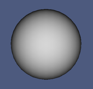
We will work with a single component, a sphere:
- Select the document node in the Model Tree.
- Create a new Part Design > Body.
- Create a new Part Design > Sketch on the XY plane.
- Create a Sketch > Geometries > Arc by center.
- Constrain the arc center on the sketch origin.
- Constrain the end points on the X axis.
- Constrain the radius to "5 mm".
- Create a Sketch > Geometries > Line.
- Constrain the end points of the line to the end points of the arc.
The sketch is fully constrained now:
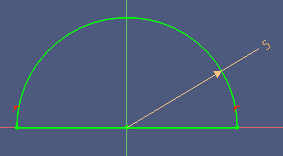
- Leave the sketch.
- Create a new Part Design > Revolution.
- Select the horizontal sketch axis and click OK.
- Collapse the Body nodes.
Now wrap the body with an Assembly:
- Switch to the Assembly 3 workbench.
- Create a new Assembly.
- Set the Label property to "Sphere".
- Drag the Body on the Sphere node.
- Collapse the child nodes.
- Move the Sphere to the Repository.
- Hide the Sphere.
- Save a copy of the project file under the name "move-001.fcstd".
The components have been created, now we will create the nested assembly structures.
Now will add components into the assembly containers.
If you want to quick-start from here, load the file move-002.fcstd, and save it under the work file name "move.fcstd".
- Right-click the Sphere component in the Repository, then click Link actions > Make link.
- Activate the View Tab on the Property Panel.
- Set Override Material to "true".
- Select a color of your choice into the Shape Material property.
- Drag the Sphere 001 on the Project Assembly Container.
Now the second sphere.
- Right-click the Sphere component in the Repository, then click Link actions > Make link.
- Activate the View Tab on the Property Panel.
- Set Override Material to "true".
- Select a color of your choice into the Shape Material property.
- Activate the Data Tab on the Property Panel.
- Expand the Placement > Position property.
- Set the z property to "-15 mm".
- Drag the Sphere 002 on the Level 2 Assembly.
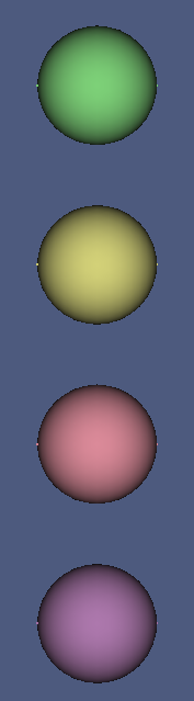
Repeat from step 39 for the components Sphere 3 at z = -30 mm, and Sphere 4 at z = -45 mm. Move them into the Level 2 and Level 3 assemblies.
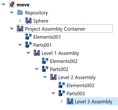
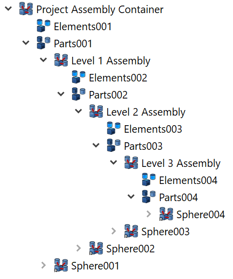
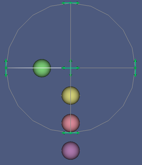
You should now have the following arrangement:
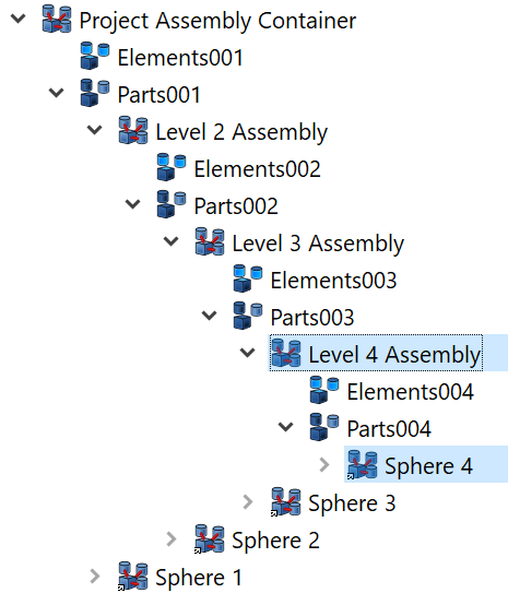
And the Model Tree structure:
- Collapse the child nodes of Parts001.
- Save a copy of the work file under the name "move-003.fcstd".
In this section we will move components in space.
You have already seen the Placement > Position property work as expected. Now we will work the the Axial Mover, Assembly Part Mover and the Quick Mover tools.

If you want to quick-start from here, load the file move-003.fcstd, and save it under the work file name "move.fcstd".
Moving Sphere 1
We will start with the Axial Mover on Sphere 1.

- Press 1 on the keyboard to switch to the front view.
- Select Sphere 1 in the Model Tree. This object is a Part of the Project Assembly Container.
- Click the menu Assembly3 > Axial move part.
A tool appears in the 3D window that looks and works exactly like the standard Freecad Transform tool.
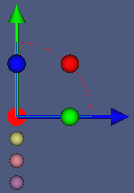
- Drag the blue arrow to the side, then press Esc.
The topmost sphere moved as expectd.
- Undo the move command.
Now we will try the Assembly Part Mover

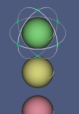
- Press 0 to get to the standard isometric view.
- Select Sphere 1 in the Model Tree.
- Click the menu Assembly3 > Axial move part.
A tool with a set of three perpendicular rings and arrows appears in the 3D window.
- Press 1 to show the standard front view.
- Drag the mover arrows in the center to the side, then
The topmost sphere moved as expectd.
- Note that the Project Assembly Container is highlighted in the Model Tree.
This indicates that the node is being edited.
- Press Esc.
- Undo the move command.
If you drag an arrow cross of the Assembly Part Mover, you can move the part in the plane of the arrow cross. If you drag a ring, the part is rotated about the ring axis (which is not easily seen on a sphere…).
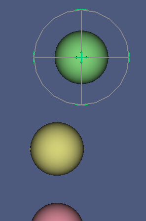
Now we will try the Quick Mover.
- Select Sphere 1 in the Model Tree.
- Click the menu Assembly 3 > Quick move.
- Move the mouse pointer. The selected object follows the pointer until you click.
- Note that the parent node of the moved object is selected, Parts001.
- Undo the move command.
Three different tools to move objects. Choose the one that suits you preferences best.
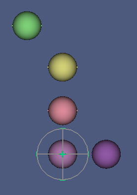
Level 1 Subassembly
Repeat the move tests with Level 2 Assembly, a member of the Project Assembly Container like Sphere 1.
The results are similar, the whole subassembly is moved. The difference is that the mover tools now appear over Sphere 1, which is also a member of the Project Assembly Container.
Another difference: The Assembly Part Mover changed its size to accommodate the size of the assembly.
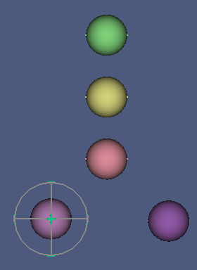
Sphere 2
- Select the node Sphere 2.
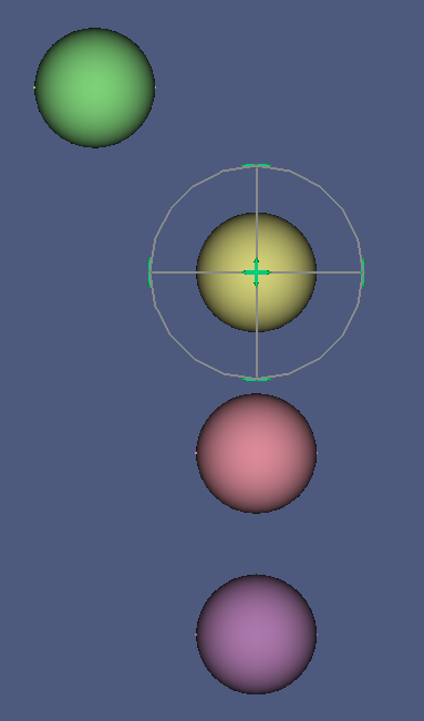
- Activate the Axial Mover.
The mover tool appears centered over Sphere 2.
- Drag on the tip of the blue arrow.
Surprisingly, the whole Level 1 Subassembly is moved.
- Try the Assembly Part Mover.
Same result.
- Try the Quick Mover.
Same result.
- Undo the move commands.
The mover tools are centered over the sphere, but the whole Level 1 Subassembly is moved.
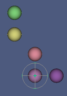
Level 3 Assembly
- Try the mover tools on Level 3 Assembly.
The mover tools are centered over Sphere 1.
The whole Level 2 Assembly is moved.
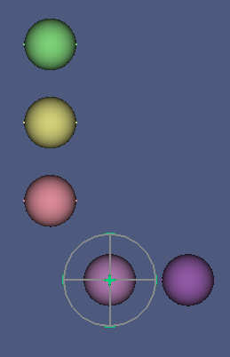
Sphere 3
- Try the mover tools on Sphere 3.
The mover tools are centered over Sphere 3.
Level 2 Assembly is moved.
Level 4 Assembly
- Try the mover tools on Level 4 Assembly.
The mover tools are centered over Sphere 4.
Level 2 Assembly is moved.
Sphere 4
- Try the mover tools on Sphere 4.
The mover tools are centered over Sphere 4.
Level 2 Assembly is moved.
Conclusion
Although the mover tools seem to behave "erratic" when subassemblies or components in subassemblies are moved, but there is a method to the madness:
- Components in the highest level (zero) assembly are moved as usual.
- Components in subassemblies always move the Level 2 Assembly.
This does not make much sense if you select nodes in the Model Tree to move them, but it does make perfect sense if you select components in the 3D window: Because assembly containers have no visual representation in the 3D window, it cannot be decided when you select Sphere 4 whether you want to move the sphere, or its parent, Level 4 Assembly, or its parent Level 3 Assembly, or its parent Level 2 Assembly. The only certainty is that the first level assembly, the Project Assembly Container, can never be moved, because this element provides the project-wide global coordinate system.
But what if you really wanted to move a component further down the hierarchy? There are two options:
- Drag the parent assembly container on the project document node, move your components, and drag the parent assembly container back to where it belongs.
- Use the double-selection trick.
The double selection trick is simple: Select the object to be moved, and its parent container. But before checking that out, let's add another sphere to the Level 4 Assembly:
- Right-click the Sphere in the Repository, then click Link actions > Make link.
- Rename it to Sphere 4b.
- Drag it on Level 4 Assembly.
- Switch to the View Tab on the Property Panel.
- Set Override Material to "true".
- Select a color of your choice into the Shape Material property.
- Switch to the Data Tab.
- Set the Placement > Position > x property to "15 mm".
- Set the z property to "-45 mm".
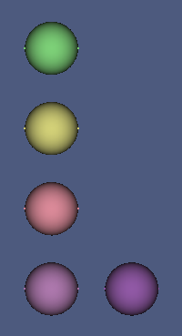
The new sphere should appear at the side of Sphere 4. Now Let's test it.
- Select Sphere 4 and Level 4 Assembly.
- Move the sphere somewhat to the right.
That works, Sphere 4 moved.
- Undo the move command.
- Select Sphere 4 and Level 3 Assembly.
- Select the mover tool of your choice from the Assembly3 menu.
- Move the sphere somewhat to the right.
Level 4 Assembly moved.
- Undo the move command.
- Select Sphere 4 and Level 2 Assembly.
- Select the mover tool of your choice from the Assembly3 menu.
- Move the sphere somewhat to the right.
Level 3 Assembly moved.
- Undo the move command.
- Select Sphere 4 and Project Assembly Container, which is the first level assembly.
- Move the sphere somewhat to the right.
Level 2 Assembly moved.
The examples in the previous section showed that there is a set of simple rules, followd by the movers:
1. The selected component low in the hierarchy is used as a grip.
2. The Assembly below the higher selected component is moved.
3. If only one component was selected, the highest assembly is considered to be selected implicitly.