The Freecad User Book
Links and Link Arrays
Tags
Freecad, Assembly 3, Link, Link Array, Constraint, Constraint Connector, Subassembly.
Freecad Version Info
OS: Windows 10 (10.0)
Word size of OS: 64-bit
Word size of FreeCAD: 64-bit
Version: 0.19.17089 +1543 (Git)
Build type: Release
Branch: LinkStage3
Hash: 950c082111ae5ebeefb4dddc90a80dc9b54b2408
Python version: 3.6.8
Qt version: 5.12.1
Coin version: 4.0.0a
OCC version: 7.3.0
Locale: English/United States (en_US)
Files
Videos
In the videos the outdated term "mating connectors" was used for "constraint connectors". Additionally, the file old prefix "asm3-link-1" instead of "link".
- link-001
- Local Repository
- link-002
- Washer Component
- link-003
- Nut Component
- link-004
- Screw Component
- link-005
- Block Component
- link-006
- Nut & Washer Subassembly
- link-007
- Bolt & Washer Subassembly
- link-008
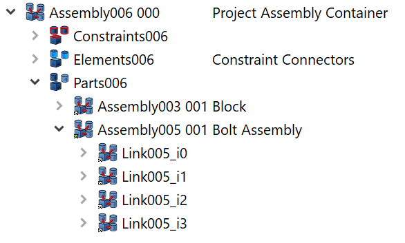
- Project Assembly Container
- link-009
- Mounting the Bolt Subassembly
- link-010
- Mouting the Nut Subassembly
- link-011
- Geometry Modifications and Constraint Enforcements
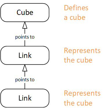
The Assembly 3 workbench introduces a powerful new concept: the Link Object. The Link enables lightweight copies of an object. A link stands for and points to a link source (or link target) object, which provides the geometric definition. If the definition is changed, all links "inherit" these changes.
Links work quite similar to a web page link: Many users can follow the same HTML link and view a copy of the web page in their browsers. If the page author modifes and updates the page file on the server, all users will get the new content as soon as they refresh their page view.
The Link object introduces some own properties, they appear in a black font. Other properties are inherited from the link source object, these are shared among all links. These appear in a green font. If a shared property is changed (such as the length of a pad), all Link objects will reflect this change immediately. Other link properties hide or shadow a Link Source property with the same name, such as visibility or position. As a result, each Link object can appear in a different location and orientation, or be individually hidden or made visible.
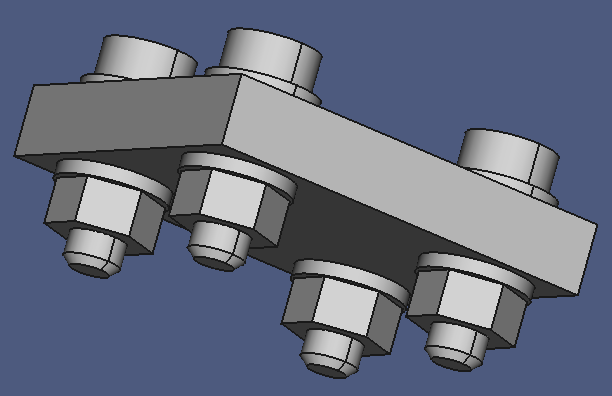
To demonstrate the Link functionality, we are going to create a small repository of standard components, a screw, a washer, a nut, and a block with a few bore holes to accomodate a screw/nut/washer combination. Multiple instances of these standard parts are will be used during project assembly to demonstrate efficient work with Link Arrays.
Note that Links are not copies. In a way this is similar to the mainstream Freecad Clone, but the Assembly 3 Link object appears to be much more powerful.
We will also build subassemblies and learn that a subassembly, just like a component or a project assembly container, is an ordinary Assembly object. While a component has only external (public) constraint connectors, a project assembly container has only internal connectors, and a subassembly has both internal and external constraint connectors.
I used my naming convention for the Link objects, exploiting Freecad's numbering feature to create unique object names and preserving the link source object name. This convention served me well, but you can use your own convention or accept the names suggested by Freecad.
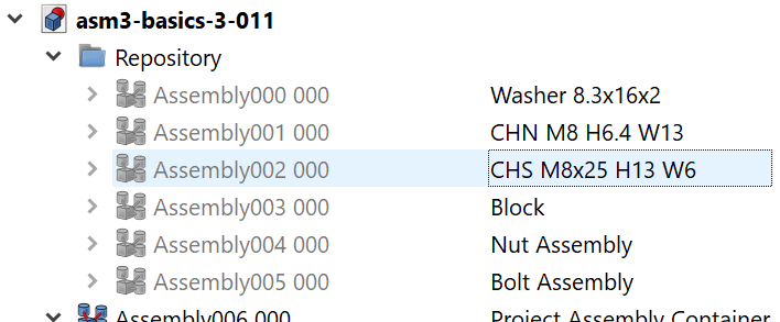
The Local Repository
Related materials:
A repository is a sort of library for components. The idea is to re-use existing and proven designs. In this tutorial, we will implement a local repository within the project file, just to keep things simple. In an upcoming tutorial, we will move the standard components from the project file to an external library file.
Note that repository components don't have to be imported from external files, you can keep everything in a single project file. This makes design exchange rather straight-forward.
So, let's begin!
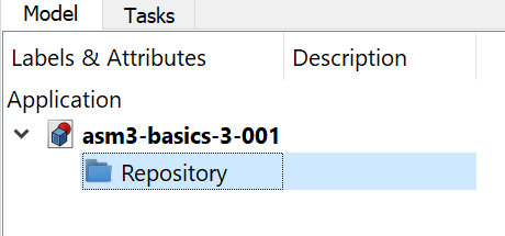
- Create an empty project file, and save it under the name "link.fcstd".
- Right-click the project root node in the Model Tree, then click Create group....
- Change the Label propety to "Repository".
- Save a copy under the name "link-001.fcstd".
Figure 1
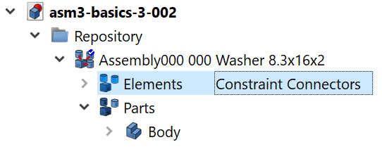
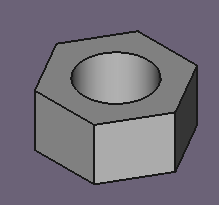
The Washer
The Nut
Related materials:
Creating the nut component follows the same workflow, so nothing new in this section. If you don't have the time or patience, proceed to the assembly of components.
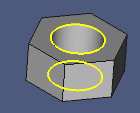
Like the washer, the nut has two constraint connectors, the upper and lower face constraint connectors. They are bound to the upper and lower edges of the tapped hole.
- Switch to the Part Design workbench.
- Select the project root node in the Model Tree.
- Create a new Body.
- Create a new Sketch on the XY plane.
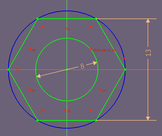
- In the sketcher, draw a circle on the sketch origin.
- Set the diameter constraint to 8 mm.
- Draw a hexagon on the sketch origin.
- Constrain the distance between two parallel sides to 13 mm.
- Close the sketch.
- Create a Pad with a length of 6.4 mm.
Now we will wrap the Part Design Body in an Assembly container:
- Switch to the Assembly 3 workbench.
- Create a new Assembly.
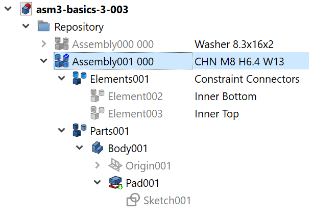
- Rename it to "Assembly001 000".
- Set Label2 to "Hex Nut M8 K13 H6.5".
- Drag Body001 and drop it on Assembly001 000.
- Set Label2 of Elements001 to "Constraint Connectors".
The next steps define the constraint connectors for the nut, and bind them to elements of the nut geometry:
- In the 3D window, select both upper and lower edgesof the nut.
- Drag Pad001 and drop it on the Constraint Connectors node.
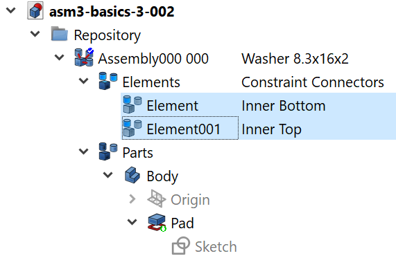
- Set the Label2 of Element001 to "Inner Lower Edge".
- Hide the Sketch001.
- Set Label2 of the connector child nodes nodes to "Inner Bottom" and "Inner Top".
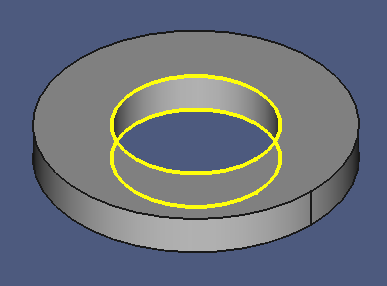
- Select the new connectors, or hover the mouse over their nodes, and check their correctness in the 3D window.
The finished component is moved to the local repository:
- Drag Assembly001 000 and drop it on the Repository.
- Hide Assembly001 000.
- Save the work to the file "link-003.fcstd".
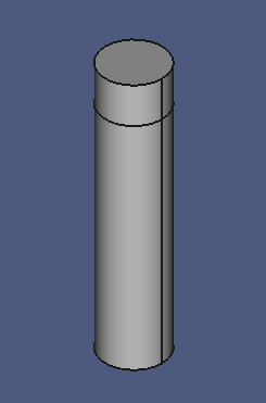
The Screw
Related materials:
One again, the same workflow:
- Switch to the Part Design workbench.
- Select the project root node in the Model Tree.
- Create a new Body.
- Create a new Sketch on the XY plane.
- In the sketcher, draw a circle on the sketch origin.
- Set the diameter constraint to 8 mm.
- Close the sketch.
- Create a new Pad with a length of 5 mm, reversed.
- Set the Label2 property of the new Pad to "Shaft".
- Select the bottom face of the shaft.
- Create a new Sketch.
- Click the menu Sketch > Geometries > External Geometry > Defining.
- Click the circumference line of the circle. This creates a new circle in the sketch, defined by the external lower edge of the shaft pad.
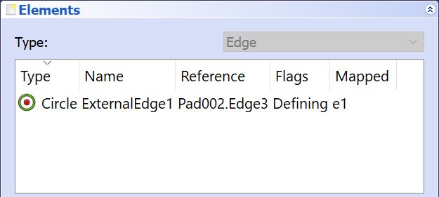
A more robust alternative to define the circle would have been to use the sketch that defined the pad.
- Close the sketch.
- Create a Pad with the lenght of 30 mm.
- Set Label 2 to "Thread".
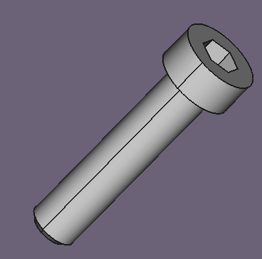
Now the head:
- Create a new Sketch on the XY plane.
- Draw a circle with the center on the sketch origin.
- Constrain its diameter to 13 mm.
- Close the sketch.
- Create a new Pad with a length of 6 mm.
- Set Label2 to "Head".
- Select the upper face of the head in the 3D window.
- Create a new Sketch.
- Draw a hexagon with the center on the sketch origin.
- Constrain the distance between two parallel lines to 6 mm.
- Close the sketch.
- Create a new Pocket with a length of 5 mm.
- Set Label2 of Pocketto "Wrench Pocket"
- Select the bottom edge of the shaft.
- Create a new Chamfer.
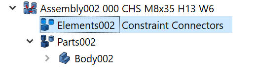
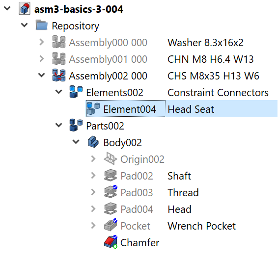
Wrapping the Body in an Assembly container:
- Switch to the Assembly 3 workbench.
- Create a new Assembly.
- Set Label to "Assembly002 000".
- Set Label2 "Cylinder Head Screw M8 x 35".
- Drag Body002 and drop it on Assembly002 000.
- Set Label2 of Elements002 to "Constraint Connectors".
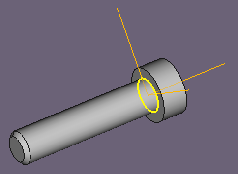
Now we will define an constraint connector for the screw. We have chosen to bind the connector to the upper edge of the shaft here. A more robust selection would be the sketch on which the the shaft pad depends.
- Show Pad002. This hides all other features of the body.
- Select the upper edge of the shaft pad.
- Drag Pad002 and drop it on the Constraint Connectors group node.
- Set Label2 of Element004 to "Head Seat".
- Show the Chamfer feature.
- Select the Head Seat connector, or hover the mouse over the node to check the constraint connector for correctness.
Move the component to the repository:
- Drag the Assembly002 000 node and drop it on the Repository node.
- Hide Assembly002 000.
- Save the work to the file "link-004.fcstd".
The Block Component
Related materials:
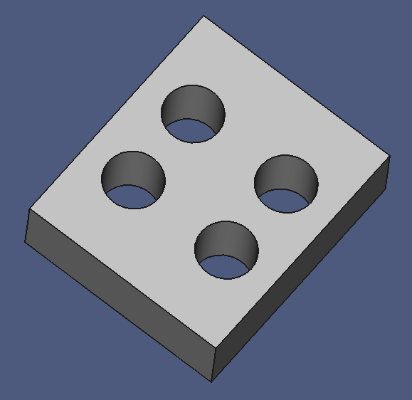
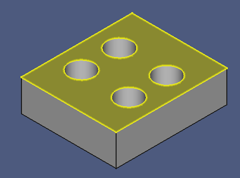
The Block is a simple cuboid with four circular holes for the fasteners. Once again, the same workflow.
- Switch to the Part Design workbench.
- Select the document root node in the model tree.
- Create a new Body.
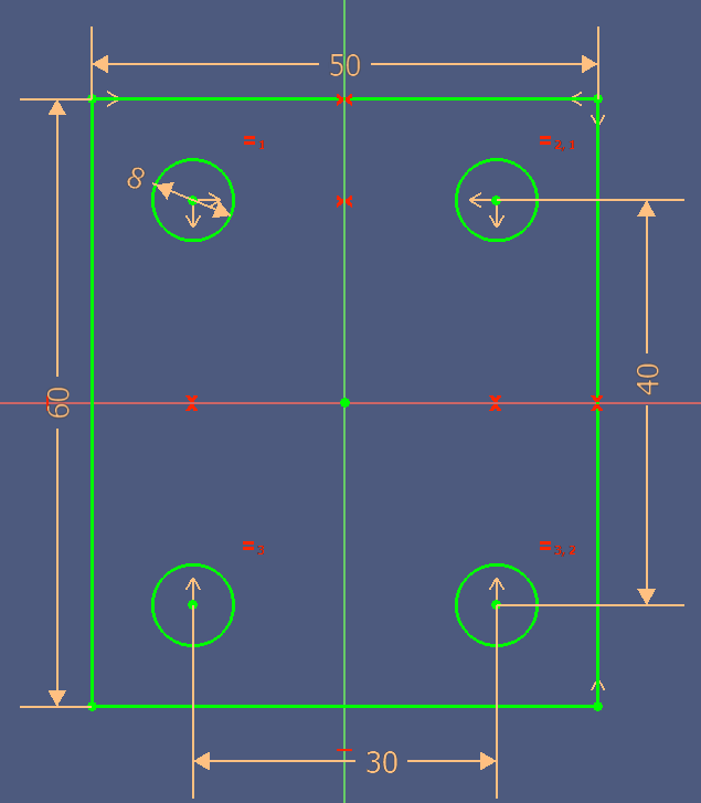
- Create a new Sketch on the XY plane.
- Create 4 circles around the sketch origin.
- Constrain them to be equal in size.
- Constrain the diameter to 8 mm.
- Arrange them symmetrically.
- Draw a rectangle, centered around the sketch origin.
- Create dimension constraints.
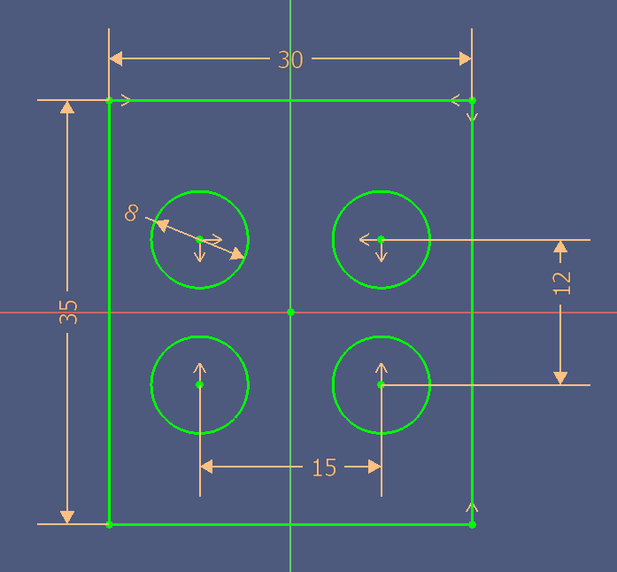
- Name the constraints as in the following image:
- Close the sketch.
- Create a new Pad with a length of 10 mm, reversed.
Wrap the component in an Assembly container:
- Switch to the Assembly 3 workbench.
- Create a new Assembly.
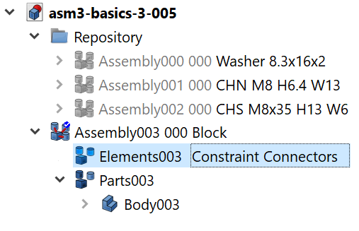
- Set Label to "Assembly003 000".
- Set Label2 to "Mounting Block"
- Drag Body003 on Assembly003 000.
- Set Label2 of Elements003 to Constraint Connectors.
Bind the constraint connectors to geometry elements:
- Tilt the block slightly forward, so that both upper and lower bore hole edges are visible.
- Select all eight upper bore hole edges. Maintaining a specific selection order helps to identifiy the elements in the Constraint Connectors group later.
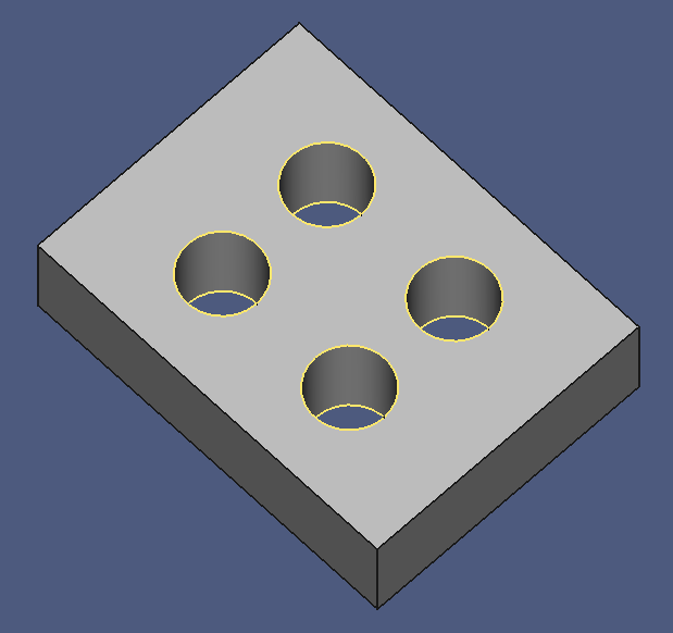
- Drag Pad004 on the Constraint Connectors node.
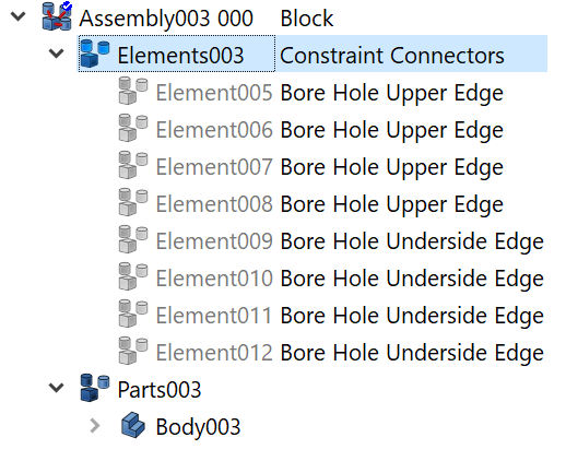
- Select the first four Constraint Connectors 003 child nodes.
- Verify in the 3D window that they are all on the upper side of the block.
- Set their Label2 property to "Bore Hole Upper Edge ".
- Select the remaining four Connectors.
- Set their Label2 to "Bore Hole Lower Edge".
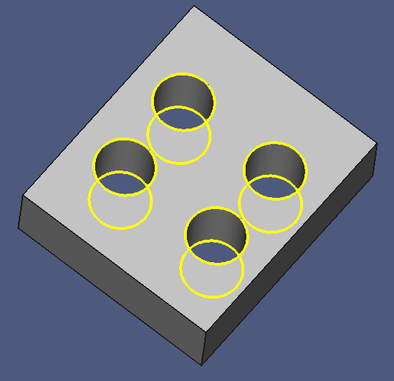
- Check the correctness of the constraint connectors in the 3D window.
Move the new component to the repository:
- Drag Assembly003 000 on the Repository.
- Hide Assembly003 000.
- Save the work to the file "link-005.fcstd".
The Block component is now finished.
Subassemblies
In order to minimize work, we will not assemble all the components individually, but create subassemblies first.
Note that project assembly, subassembly and component are technically identical — they all are Assembly objects.
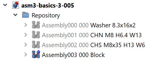
Nut & Washer Subassembly
Related materials:
- Switch to the Assembly 3 workbench.
- Create a new Assembly.
- Append " 000" to the Label.
- Set Label2 to "Nut Assembly".
- Select the washer component.
- Copy Label2.
- Right-click the washer component, click Link actions > Make link..
- Paste the new link's Label2 content.
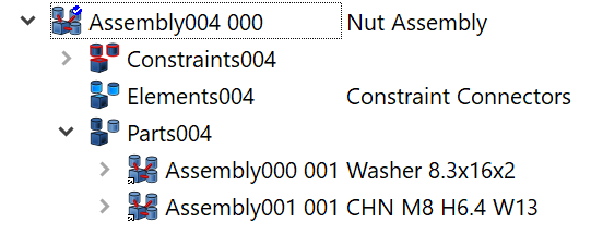
- Select the nut component.
- Copy its Label2.
- Right-click the nut component, click Link actions > Make link.
- Paste the new link's Label2 content.
- Select the two new Link objects, and drag them on the nut assembly node. They are moved to the Parts004 node.
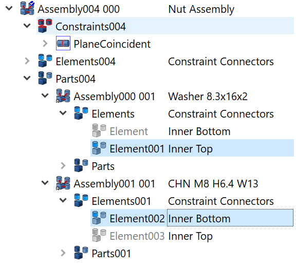
Now we are going to define the constraints between the constraint connectors of the components. Each component has two connectors, so we have to decide which of them are to be mated by the constraint.
- Expand the Constraint Connectors node of the two subassemblies.
- Select the nut's Inner Bottom connector.
- Select the washer's Inner Top connector.
- With both connectors selected, click the Plane Coincident button on the Assembly 3 Constraints toolbar. This creates the new Constraints and Plane Coincident nodes in the model tree.
The position of components changed, the nut now sits on top of the washer:
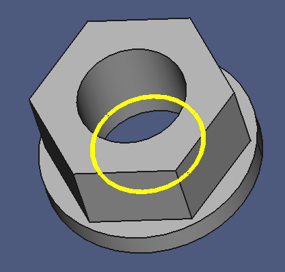
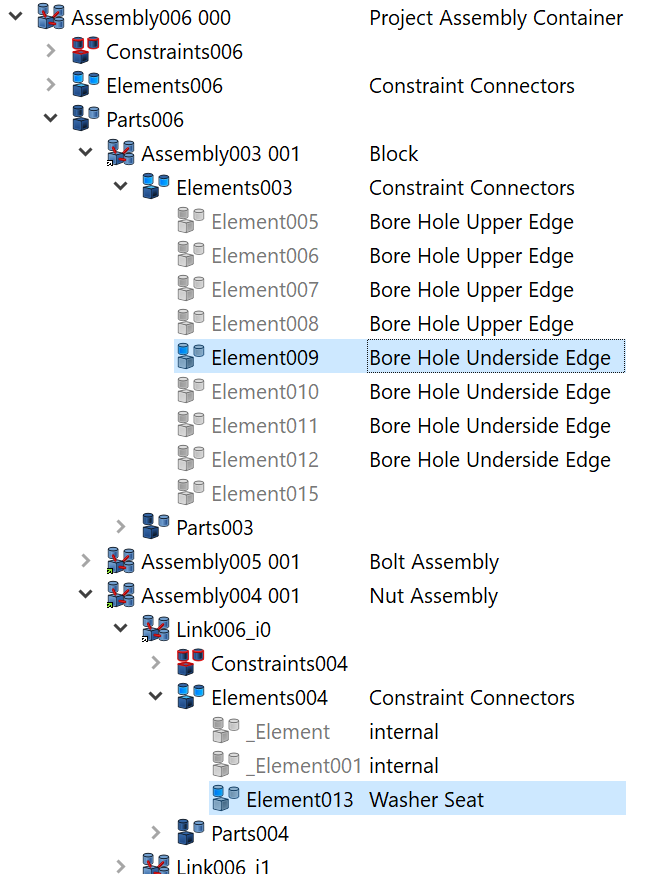
The next step creates an external constraint connector on the nut subassembly, and binds it to the inner lower edge of the nut. This connector will be used to mate the subassembly to other Assembly objects, therfore it is called public or external constraint connector.
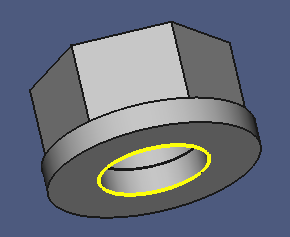
- Set Label2 of Elements004 to "Constraint Connectors".
- Drag the Inner Bottom connector of the washer on this Constraint Connectors node.
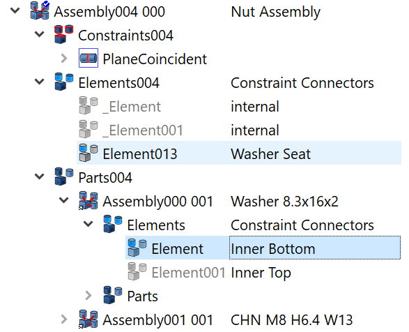
- Set Label2 of Element013 to "Washer Seat"
A text in the Label2 property of a constraint connector indicates that the connector is intended for external use. The other are internal connectors, usually not of interest outside this subassembly. Alternatively, you can set a special text like "internal" to internal connectors.
Final steps:
- Drag Assembly004 000 on the Repository node. This collapses the node conveniently.
- Hide Assembly004 000.
- Save a copy under the name "link-006.fcstd".
Bolt & Washer Subassembly
Related materials:
- Switch to the Assembly 3 workbench.
- Create a new Assembly.
- Append " 000" to the Label.
- Set Label2 to "Bolt Assembly".
- Select the washer component.
- Copy Label2.
- Right-click the washer component, click Link actions > Make link..
- Paste the new link's Label2 content.
- Select the screw component.
- Copy its Label2.
- Right-click the screw component, click Link actions > Make link.
- Paste the new link's Label2 content.
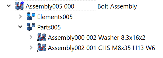
- Select the two new Link objects, and drag them on the bolt subassembly node. They are moved to the Parts004 node.
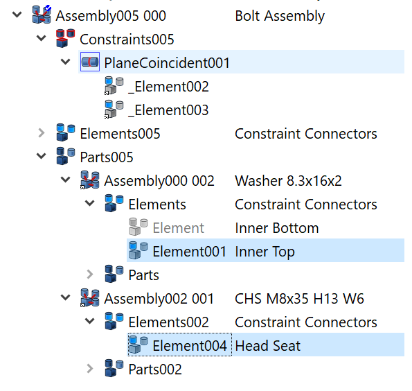
Now we are going to define the constraints between the constraint connectors.
- Expand the Constraint Connectors node of the two subassemblies.
- Select the screw's Head Seat connector.
- Select the washer's Inner Top connector.
- With both connectors selected, click the Plane Coincident button on the Assembly 3 Constraints toolbar.
The position of components change, the screw now sits on top of the washer.
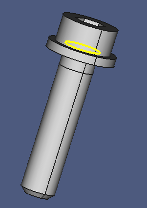
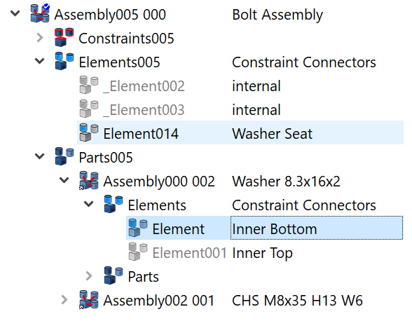
Create the public constraint connector for the subassembly:
- Set Label2 of Elements005 to "Constraint Connectors".
- Drag the Inner Bottom connector of the washer on this Constraint Connectors node.
- Set Label2 of Element013 to "Washer Seat".
Final steps:
- Drag Assembly005 000 on the Repository node. This collapses the node conveniently.
- Hide Assembly005 000.
- Save a copy under the name "link-007.fcstd".
At this stage, the subassemblies have been created. Now we are going to assemble on the project level.
Project Assembly
In this section we will create the project assembly container, then insert components and subassembly, and define geometry constraints between them.
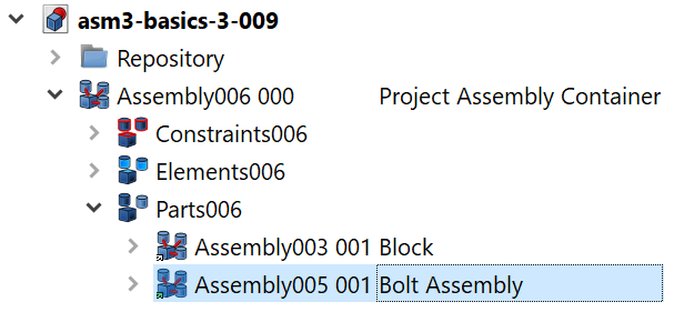
Project Assembly Container
In this section we will create the assembly container and add the Block component.
Related files
- Switch to the Assembly 3 workbench.
- Create a new Assembly.
- Set Label2 to "Project Assembly Container".
- Select the Block component in the Repository group.
- Copy the Label2 text.
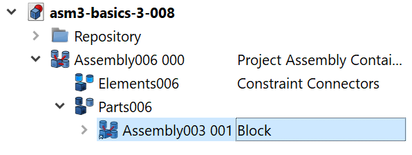
- Right-click the Block component, click Link actions > Make link. A new Assembly Link object is created at the end of the model tree.
- Select Assembly003 001, and paste the Label2 text.
- Drag the Block on the Project Assembly Container. The block assembly is moved to the Parts006 node.
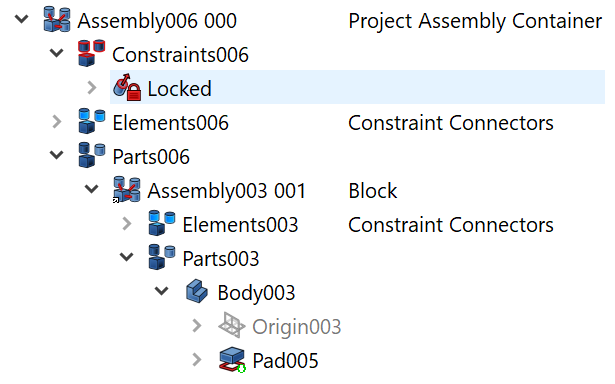
- Select the top face of the block component.
- Click the Lock Constraint button on the Assembly 3 Contraints toolbar. This prevents the block to move when it is constraint relation with other components is created later on.
Side note: This step appears in a follow-up video.
- Save a copy under the name "link-008.fcstd".
A project assembly container is usually not reused in other projects and/or assemblies, so we don't have to define any public constraint connectors. Of course, they can always be added after the fact.
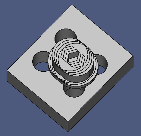
Mounting the Bolt Assembly
Related files
In this section we will mount the bolt subassembly to the block component using assembly constraints.
- Make sure the Assembly 3 workbench is active.
- Select the Bolt Assembly.
- Copy Label2.
- Right-click the Bolt Assembly, click Link actions > Make link. An instance of the bolt subassembly appears over the block component.
- Paste Label2 on Assembly005 001.
- Drag the Bolt Assembly on the Project Assembly Container. It is moved under the Parts006 group node.
NOTE: At this point, the video shows how to add the forgotten Lock Constraint on the top face of the Block component.
We continue with creating a Link Array with four instances of the Bolt Assembly:
- Select the Bolt Assembly.
- Change Element Count to "4". Four instances of the bolt assembly appear in the 3D window, scattered along the x axis.
- Expand the bolt assembly node. Verify that four Link instances of the bolt assembly appear as child nodes under the bolt assembly.
Setting the Element Count property to a value of 1 or greater changes an ordinary Link node to a Link Array node, with the array elements appearing as child nodes. Each link array element can be considered an ordinary Link object, with its own properties for position and visibility. This means that each Link Array element can be positioned individually. This Assembly 3 feature comes in very handy where multiple instances of a standard component (like fasteners) have to be placed, and saves a lot of vertical space in the model tree.
In the next steps we will position the Bolt & Washer links on the Block with the help of Assembly Constraints:
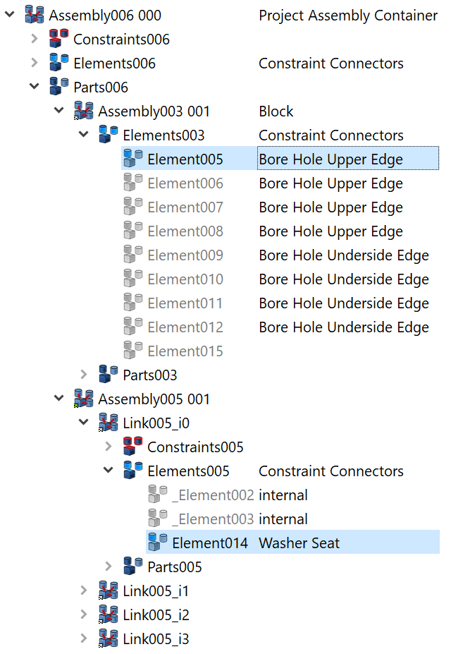
- Expand the Constraint Connectors node on the Block component.
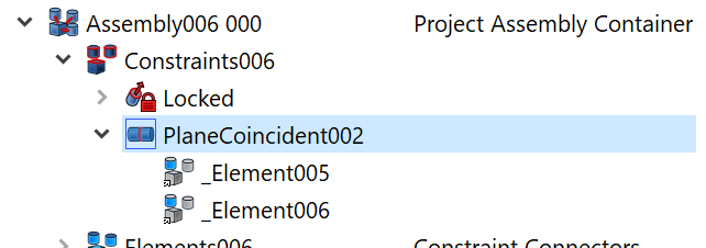
- Expand the Constraint Connectors on the first (next) Link element of the Bolt Assembly.
- Use the visual feedback in the 3D window to identfiy the proper constraint connectors on the components.
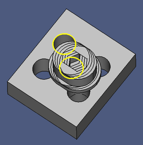
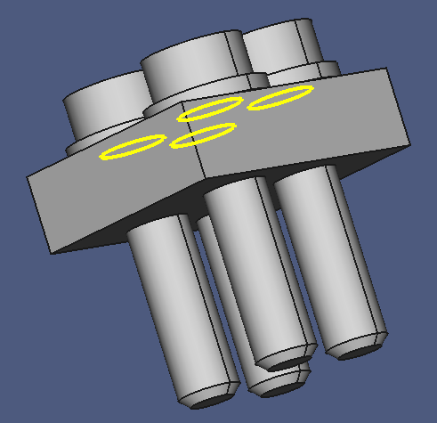
- Select the Washer Seat on the Bolt Assembly.
- Select the first Bore Hole Upper Edge on the Block component.
- Click the Plane Coincident button on the Assembly 3 Contraints toolbar. If you have the menu Assembly3 > Auto-recompute function on, bolt and washer should jump to their new location.
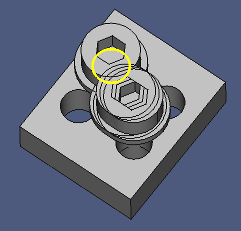
The new constraint element appears under the constraints group node of the Project Assembly Container.
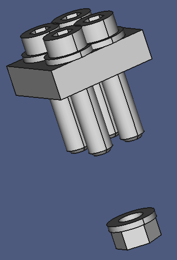
Repeat the last three steps for the rest of the bolt assemblies and inspect the result.
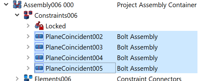
- Select the four new PlaneCoincident constraint nodes under the Project Assembly Container.
- Notice how they are highlighted in the 3D window.
- Set their Label2 to "Bolt Assembly".
Cleanup:
- Collapse all open nodes.
- Save a copy under the name "link-009.fcstd".
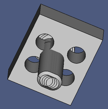
Mounting the Nut Assembly
Related files
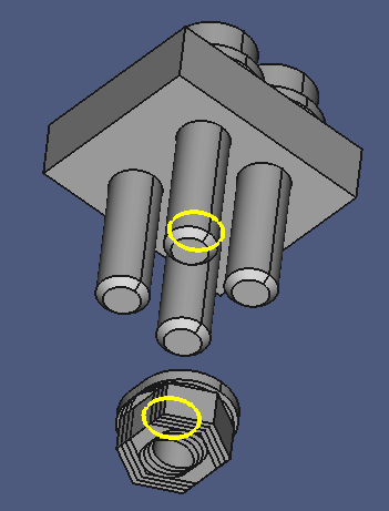
In this section we will attach the nut subassembly to the underside of the block, using a Plane Coincident constraint.
- Make sure to have the Assembly 3 workbench active.
- Create a Link object from the Nut Assembly, and drag it on the Project Assembly Container.
- Use the Assembly 3 Axial Move Part tool to move the Nut Assembly below the other components, and rotate the washer side up.

It is not necessary to bring the washer seat plane exactly parallel to the underside of the block, but their angle should be smaller than 90 degree — otherwise the constraint solver might decide to mate the nut assembly in the wrong orientation. Then you would have to fiddle with the Angle....
- Rotate the scene to get a clear view on the underside an the nut assemlies.
- Set Element Count to "4".
- Expand the block constraint connectors. We are interested in the Bore Hole Underside Edge connectors.
- Select the first (next) of these.
- Expand the constraint connectors of th first (next) nut assembly, and select the Washer Seat connector.
- With both connectors selected, click the Plane Coincident button on the Assembly 3 Constraints toolbar.
Nut and washer should jump to the desired place on the block underside.
Repeat the last three steps for the remaining three nut assemblies.
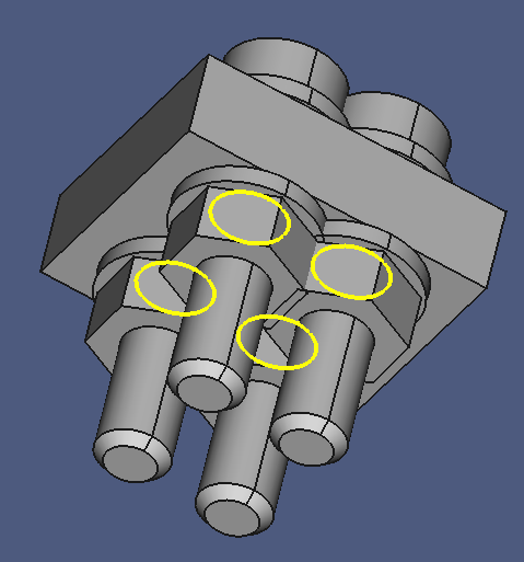
- Select the four new Plane Coincident constraints under the Project Assembly Container.
- Set their Label2 to "Nut Assembly".
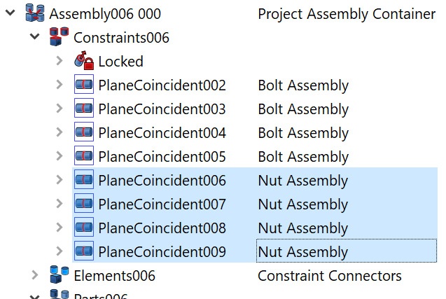
- Select all Nut Assembly constraints, and check them in the 3D view.
Cleanup:
- Collapse all open nodes.
- Save a copy under the name "link-010.fcstd".
Geometry Modifications and the Benefit of Constraints
Related files
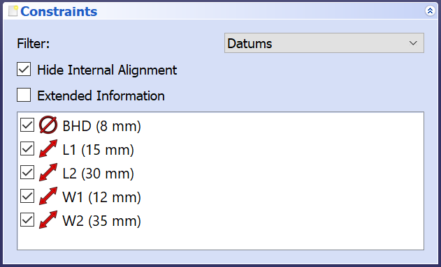
You certainly have noticed that the block dimensions and hole distances are much too small for the fasteners. This can be easily corrected:
- Select the sketch Repository > Assembly003 000 > Parts003 > Body003 > Pad005 > Sketch006.
- On the Property Panel, Modify the datum constraint values according to the following figure:
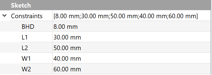
If you have the Auto-Recompute function active, the scene should update with every value change committed. If not, execute the menu Assembly3 > Solve constraints.
In the next steps we will reduce the screw to the required length. In contrast to the steps above, where we modifed the link source object in the repository, we will now edit the object "in-place":
- Open the path Project Assembly Container > Parts006 > Bolt Assembly > Links005_i0 > Parts005 > CHS M8x35 > Parts002 > Body002.
- Select the Thread node.
- Set its Length property to "25 mm".
Length is a shared property, so the links of all screw instances is changed. Unfortunately, Label2 is a non-shared property, and its value no longer matches its dimensions. The next steps show how this can be dealt with in an efficient manner.
- Right click on the screw component node Assembly002 001 in the Project Assembly Container, then click Select lined object. This carries you directly to the screw definition object, Assembly002 000.
- Change its Label2 property to "CHS M8x25 H13 W6".
- Right-click on the Assembly002 000 node, then click Link actions > Select all links.
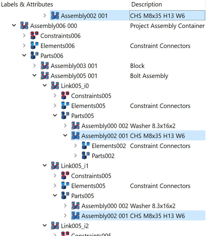
- Ctrl-click on the Description text box of the first Assembly002 link element.
This unselects the element, but the description text box has the "keyboard focus", as indicated by its dotted border.
- Press F2 to start editing, and change the text to "CHS M8x25".
- Press Enter to leave edit mode.
Notice that all selected Link elements have changed their description!
Another point of interest: The screw length does not automatically change with block thickness, so let's change that:
- Find the element that determines the block thickness. It is the Repository > Block > Parts003 > Body003 > Pad005 node with its Length property. Note the current value of 10 mm.
- Find the element that determines the length of the screw. It is the Length property of the Repository > Assembly002 000 > Parts002 > Body002 > Thread pad. Note the current value of 20 mm.
- Click on the Length value.
- Clicn on the round f(x) button to open the Formula Editor.
- Enter the text "Pad005.Length + 10 mm".
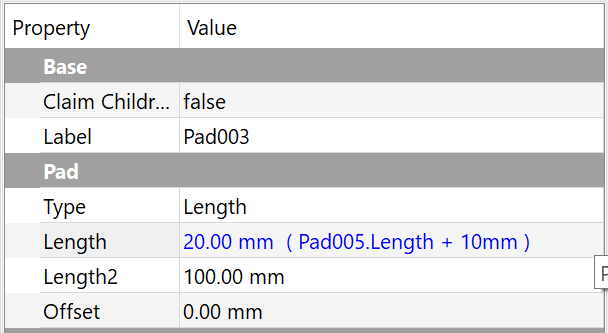
- Check the result. If OK, press Enter two times.
Now we will test whether it works, or not:
- Select Pad005.
- Change the Length property to "20 mm".
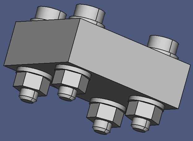
- If the nut positions did not update automatically, right-click the Block assembly, and click Recompute object.
Now the nut assemblies show up in their correct position.
Final cleanup, as always:
- Collapse all nodes.
- Save a copy under "link-011".
Conclusion
Using Links for components that occur multiple times in a model is straightforward. A Link behaves very mucht like the object it represents. Link Arrays add another level of comfort to work with multiple instances of a component, while keeping the model tree small at the same time.
Constraint Connectors are always easily accessible and selectable in the model tree, no matter how complex the model is, whereas in A2(+) type workbenches, generated geometry elements are sometimes difficult to find and select, because they can be hidden behind other features and/or components. In such a case you will have to juggle with transparency and visibility to select a geometry element for application of a constraint.
Of course, creating and maintaining constraint connectors requires some overhead, but they are really easy to create and maintain.
Mating elements with constraint connectors is as simple as using geometry elements in other assembly workbenches, such as A2(+), perhaps even simpler: Select two connectors, select the constraint, done.